p0-b0
 | TECHNICAL SPECIFICATION | Doc Number:Version: 1 | ||
| CODE: | DESCRIPTION OF MATERIAL: | Page 1 of 3 | ||
| 33kV LINE POST TYPE SILICON INSULATOR COMPLETE WITH SPINDLE | ||||

质量状态:blocked
| TECHNICAL SPECIFICATION | Doc Number:Version: 1 | ||
| CODE: | DESCRIPTION OF MATERIAL: | Page 1 of 3 | ||
| 33kV LINE POST TYPE SILICON INSULATOR COMPLETE WITH SPINDLE | ||||
| ITEM | TECHNICAL DESCRIPTION | UNIT | REA REQUIREMENTS | BIDDERS OFFER |
| 1 | Type | 33kV Silicon Rubber Line Post Insulator with bottom metal fittings complete with spindle, washer, nut & lock nut for Horizontal Mounting. | ||
| 2 | Nominal Voltage | kV | 33 | |
| 3 | Highest System Voltage | kV | 36 | |
| 4 | Nominal Specific Creepage Distance | mm/kV | 25 | |
| 5 | Spindle Dimensions | Mm | M20 x 250 | |
| 6 | Failing load (bend) $P_0$ | kN | 10 | |
| 7 | Failing load (Torsion) | Nm | 2.5 | |
| 8 | Power frequency wet withstand voltage | $kV_{r.m.s}$ - 1 minute | 70 | |
| 9 | Lightning Impulse withstand voltage (peak) | kV | 170 | |
| 10 | Max Nominal Diameter of Insulating Part | Mm | 245 | |
| 11 | Material of insulating part | High Temperature Vulcanised Silicon rubber | ||
| 12 | Material of metal parts | Hot Dip Galvanised Steel | ||
| 13 | Applicable Standards | BS 137, IEC 61109, IEC61952, IEC60815-3 | ||
| 14 | Altitude above sea level | 1400 | ||
| 15 | Operating ambient temperature | °C | -1 to 40 | |
| 16 | Relative humidity | % | 85 | |
| 17 | Previous type test report/ certificates to be provided with bid | Yes/No | No | |
| 18 | Routine test results/certificates to be provided on delivery | Yes/No | Yes | |
| 19 | Drawings showing dimensions of insulators offered to be provided with bid | Yes/No | Yes | |

| TECHNICAL SPECIFICATION | Doc Number:Version: 1 | ||||
| CODE: | DESCRIPTION OF MATERIAL: | Page 2 of 3 | ||||
| 33kV LINE POST TYPE SILICON INSULATOR COMPLETE WITH SPINDLE | ||||||
| 20 | Tenderer shall provide previous 5000 hours ageing test certificate/results according to IEC 61109, with the bid | Yes/No | Yes | |||
| 21 | Quality Assurance Certification to be provided with bid | Yes/No | Yes | |||
 | ||||||

OTHER REQUIREMENTS
Markings
Insulators shall be marked with the specified Electro-mechanical or mechanical failing load e.g. U70 BL.
Insulators shall have indelible manufacturer’s trademark and date of manufacture.
Special Clause
Tenderers may submit alternative offers which may be of financial or technical benefit to REA.
| TECHNICAL SPECIFICATION | Doc Number:Version: 1 | ||
| CODE: | DESCRIPTION OF MATERIAL: | Page 1 of 2 | ||
| INSULATOR SILICON 33kV PIN TYPE COMPLETE WITH LARGE HEAD SPINDLE | ||||

| ITEM | TECHNICAL DESCRIPTION | UNIT | REA REQUIREMENTS | BIDDER OFFER |
| 1 | Type | 33kV silicon composite pin insulator for mounting on steel cross arms complete with spindle, washer, nut and lock nut as per drawing below | ||
| 2 | Nominal Voltage | kV | 33 | |
| 3 | Highest System Voltage | kV | 36 | |
| 4 | Nominal Specific Creepage Distance | mm/kV | 25 | |
| 5 | Min. Failing load | kN | 10 | |
| 6 | Power frequency wet withstand voltage (one minute) | $kV_{r.m.s}$ | 70 | |
| 7 | Lightning Impulse withstand voltage (peak) | $kV_{peak}$ | 170 | |
| 8 | Material of insulating part | High temperature vulcanized silicon rubber | ||
| 9 | Colour of insulating material | Grey | ||
| 10 | Material of metal parts | Hot Dip Galvanised Steel | ||
| 11 | Spindle diameter | Mm | 20 | |
| 12 | Altitude above sea level | M | 1400 | |
| 13 | Operating ambient temperature | °C | -1 to 40 | |
| 14 | Relative humidity | % | 85 | |
| 15 | Previous type test report/ certificates to be provided with bid | Yes/No | No | |
| 16 | Routine test certificate/results to be provided on delivery of insulators | Yes/No | Yes | |
| 17 | Quality Assurance Certification to be provided with bid | Yes/No | Yes | |
| 18 | Drawings showing dimensions of Insulators offered to be provided with bid | Yes/No | Yes | |
| 19 | Applicable standard(s) | IEC61109, BS 3288-2 | ||
 | TECHNICAL SPECIFICATION | Doc Number:Version: 1 | ||
| CODE: | DESCRIPTION OF MATERIAL: | Page 2 of 2 | ||
| INSULATOR SILICON 33kV PIN TYPE COMPLETE WITH LARGE HEAD SPINDLE | ||||

Figure 1.0: 33kV PORCELAIN BROWN/GREY GLAZED PIN INSULATOR DRAWINGS
All dimensions are in mm.

OTHER REQUIREMENTS
Markings
Insulators shall be marked with the specified Electro-mechanical or mechanical failing load e.g. U70 BL.
Insulators shall have indelible manufacturer’s trademark and date of manufacture.
Special Clause
Tenderers may submit alternative offers which may be of financial or technical benefit to REA
| TECHNICAL SPECIFICATION | Doc Number:Version: 1 | ||
| CODE: | DESCRIPTION OF MATERIAL: | Page 1 of 2 | ||
| 33kV STRAIN SILLICON (LONG-ROD)INSULATOR | ||||

| ITEM | TECHNICAL DESCRIPTION | UNIT | REA REQUIREMENTS | BIDDER'S OFFER | |
| 1 | Type | Strain 33kV Clevis and Tongue high temperature vulcanised silicon rubber insulator to IEC61109 | |||
| 2 | Nominal Voltage | kV | 33 | ||
| 3 | Highest System Voltage | kV | 36 | ||
| 4 | Required section length of composite insulators (Equivalent to 3-disc insulators with nominal spacing of 146mm) | mm | 438 | ||
| 5 | Minimum Lightning Impulse Withstand voltage | kV | 170 | ||
| 6 | Required Minimum Power frequency (1 minute) Withstand Voltage, wet | kV | 70 | ||
| 7 | Min failing load (kN)-Mechanical test | kN | 70 | ||
| 8 | End fitting design (ball and socket size) as per IEC 60120 | mm | 16 | ||
| 9 | Nominal specific creepage Distance | mm/kV | 25 | ||
| 10 | Insulating material | High Temperature Vulcanised Silicon rubber | |||
| 11 | Material for the rod | Epoxy resin fibre reinforced | |||
| 12 | End fittings design | Clevis and Tongue, Steel, Hot-Dip Galvanised | |||
| 13 | Altitude above sea level | 1400 | |||
| 14 | Operating ambient temperature | °C | -1 to 40 | ||
| 15 | Relative humidity | % | 85 | ||
| 16 | Applicable Standards | IEC 61109 | |||
| 17 | Quality Assurance Certification to be provided with bid | Yes/No | Yes | ||
| 18 | Routine test certificate to be provided on delivery of insulators | Yes/No | Yes | Yes | |

 | TECHNICAL SPECIFICATION | Doc Number:Version: 1 | ||||
| CODE: | DESCRIPTION OF MATERIAL: | Page 2 of 2 | ||||
| 33kV STRAIN SILLICON (LONG-ROD)INSULATOR | ||||||
| 19 | Previous type test | Type tests certificate/results to be provided with bid | Yes/No | No | ||
| Previous 5000 hours ageing test certificate/results according to IEC 61109 to be provided upon client request. | Yes/No | Yes | ||||
| 20 | Drawings showing dimensions and tolerances of Insulators offered to be provided with bid | Yes/No | Yes | |||
| DRAWING | ||||||

Markings
Insulators shall be marked with the specified Electro-mechanical or mechanical failing load e.g., U70 BL.
Insulators shall have indelible manufacturer’s trademark and date of manufacture.
Special Clause
Tenderers may submit alternative offers which may be of financial or technical benefit to REA
| TECHNICAL SP ECIFICATION | Doc Number:Version: 1 | ||
| CODE: | DESCRIPTION OF MATERIAL: | Page 1 of 3 | ||
| DROP OUT FUSE LINK 33kV ASSEMBLY COMPLETE WITH FUSE CARRIER | ||||

| ITEM | TECHNICAL DESCRIPTION | UNIT | REA REQUIREMENTS | BIDDER'S OFFER | |
| 1 | Description | 33kV Fuse link assembly complete with fuse carrier rated at 100A and NEMA Mounting Bracket to PIESA 002 | |||
| 2 | System Conditions of service | ||||
| Nominal Voltage (Un) r.m.s | kV | 33 | |||
| Maximum System Voltage (Um) r.m.s | kV | 36 | |||
| Earth | Effective & Non-effective | ||||
| Frequency | Hz | 50 | |||
| 3 | Site Conditions Of Service | ||||
| Altitude | m | 1400 | |||
| Operating Ambient Temperature | °C | -1 to 40 | |||
| Humidity | % | 85 | |||
| 4 | Rating | ||||
| Nominal Voltage | kV | 33 | |||
| Rated Current | Fuse Carrier | A | 100 | ||
| Cut Out Base | A | 200 | |||
| Fuse Element | A | 5 | |||
| 5 | Electrical Conditions | ||||
| Insulation Material Specification | Porcelain | ||||
| Dielectric Strength | |||||
| Lightning impulse withstand (1.2/50) | kV | 170 | |||
| Power frequency wet withstand voltage r.m.s | kV | 70 | |||
| 6 | Nominal specific Creepage Distance | mm/kV | 25 | ||
| 7 | Previous Type test report/certificate on complete fuse link assembly to be provided with bid | Yes/No | No | ||
| 8 | Routine tests (acceptance tests on sample Product) to be provided on delivery | Yes/No | Yes | ||

| TECHNICAL SPECIFICATION | Doc Number:Version: 1 | ||||
| CODE: | DESCRIPTION OF MATERIAL: | Page 2 of 3 | ||||
| DROP OUT FUSE LINK 33kV ASSEMBLY COMPLETE WITH FUSE CARRIER | ||||||
| 9 | General information to be provided with bid: | |||||
| Drawings and/or brochures showing outline and general arrangement and Detailed drawings of all items showing critical tolerances to be provided with bid | ||||||
| 10 | Applicable standards | PIESA 002, NRS 035SABS IEC 60282-2, SABS IEC 60186, BS 137-part 2 | ||||
 | ||||||

MARKING AND IDENTIFICATION
Markings to conform to SABS IEC 60282-2
Insulators shall be marked with the specified Electro-mechanical or mechanical failing load e.g., U70 BL.
Insulators shall have indelible manufacturer’s trademark and date of manufacture.
| TECHNICAL SPECIFICATION | Doc Number:Version: 1 | |||
| CODE: | DESCRIPTION OF MATERIAL: | Page 3 of 3 | ||
| DROP OUT FUSE LINK 33kV ASSEMBLY COMPLETE WITH FUSE CARRIER | ||||

OTHER REQUIREMENTS
There shall be no rivets in the parts that form the current path
Water shall not be able to accumulate on any part of the equipment nor shall any feature introduce moisture into any component.
The design shall incorporate all reasonable precautions and provisions for the safety of personnel concerned with the operation and maintenance of the same.
The current path shall be such that load current shall only flow through high conductive materials such as copper and its alloys. Load current shall not be permitted to flow through ferrous components, springs, or spring-loaded mechanisms.
All load current paths shall be so designed that the relevant parts of the assembly are capable of carrying the specified rated current without exceeding the permitted temperature rise in SABS IEC 60282-2
Contacts shall be based on the line contact principle and there shall be no welds on the contact parts. The construction of the Drop out fuse base and the fuse link shall ensure their mutual alignment during closure.
The solid link should have an eye and an operating tongue.
SUPPLIMENTARY NOTES
Suppliers should give sufficient information including drawings (which must be brief, clear and to the point) on how their drop out fuse designs addresses the provided requirements. Suppliers can offer better alternatives that are of cost and technical benefits to the organisations without compromising on the quality.
The drawings to be submitted by the tenderer must:
Show details of the insulator, the fuse carrier, the solid link, the upper contact, the lower contact, the cut-out base, and the bracket for fixing to either wooden or steel cross arm.
o Provided critical tolerances
All tolerances should be as per PIESA 002: 1 2000
Insulator fixing stem galvanized in accordance with SABS 763.
The gusset below the tongue is require for strength, but should not limit the usable length of the torque
The current path, shown only functionally, shall be continuous up to the terminal connector.
Galvanized in accordance with SABS 736
 | TECHNICAL SPECIFICATION | Doc Number:Version: 1 | ||
| CODE: | DESCRIPTION OF MATERIAL: | Page 1 of 3 | ||
| 11kV LINE POST TYPE SILICON INSULATOR COMPLETE WITH SPINDLE | ||||

| ITEM | TECHNICAL DESCRIPTION | UNIT | REA REQUIREMENTS | BIDDER OFFER |
| 1 | Type | 11kV Silicon Rubber Line Post Insulator with bottom metal fittings complete with spindle, washer, nut and lock nut for Horizontal Mounting. | ||
| 2 | Nominal Voltage | kV | 11 | |
| 3 | Highest System Voltage | kV | 12 | |
| 4 | Nominal Specific Creepage Distance | mm/kV | 25 | |
| 5 | Spindle Dimensions | mm | M20 x 250 | |
| 6 | Failing load (bend) $P_0$ | kN | 10 | |
| 7 | Failing load (Torsion) | Nm | 1.2 | |
| 8 | Power frequency wet withstand voltage | $kV_{r.m.s}$ - 1 minute | 28 | |
| 9 | Lightning impulse withstand voltage (peak) | kV | 95 | |
| 10 | Max Nominal Diameter of Insulating Part | mm | 210 | |
| 11 | Material of insulating part | High Temperature Vulcanised Silicon rubber | ||
| 12 | Material of metal parts | Hot Dip Galvanised Steel | ||
| 13 | Applicable Standards | BS 137, IEC 61109, IEC61952, IEC60815-3 | ||
| 14 | Altitude above sea level | 1400 | ||
| 15 | Operating ambient temperature | °C | -1 to 40 | |
| 16 | Relative humidity | % | 85 | |
| 17 | Previous type test certificates and results to be provided with bid | Yes/No | No | |
| 18 | Routine test results/certificates to be provided on delivery | Yes/No | Yes | |
| 19 | Drawings showing dimensions of insulators offered to be provided with bid | Yes/No | Yes | |

| TECHNICAL SPECIFICATION | Doc Number:Version: 1 | |||
| CODE: | DESCRIPTION OF MATERIAL: | Page 2 of 3 | |||
| 11kV LINE POST TYPE SILICON INSULATOR COMPLETE WITH SPINDLE | |||||
| 20 | Tenderer shall provide previous 5000 hours ageing test certificate/results according to IEC 61109, with the bid | Yes/No | Yes | ||
| 21 | Quality Assurance Certification to be provided with bid | Yes/No | Yes | ||
 | |||||

OTHER REQUIREMENTS
Markings
Insulators shall be marked with the specified Electro-mechanical or mechanical failing load e.g., U70 BL.
Insulators shall have indelible manufacturer’s trademark and date of manufacture.
Drawings, Test Certificate/Results and Quality Documents
Tenderer shall provide previous type test certificate/results with bid
Tenderer shall provide routine test results/ certificate on delivery of insulators
Tenderer shall provide manufacturers’ quality manual /ISO 9000 Certification
Tenderers shall provide drawings showing the dimensions of Insulators offered.
Tenderer shall provide previous 5000 hours ageing test certificate/results according to IEC 61109, with the bid
Special Clause
Tenderers may submit alternative offers which may be of financial or technical benefit to REA.
| TECHNICAL SPECIFICATION | Doc Number:Version: 1 | ||
| CODE: | DESCRIPTION OF MATERIAL: | Page 1 of 2 | ||
| INSULATOR SILICON 11kV PIN TYPE COMPLETE WITH LARGE HEAD SPINDLE | ||||

| ITEM | TECHNICAL DESCRIPTION | UNIT | REA REQUIREMENTS | BIDDERS OFFER |
| 1 | Type | 11kV silicon composite pin insulator for mounting on steel cross arms complete with spindle, washer, nut and lock nut as per drawing below | ||
| 2 | Nominal Voltage | kV | 11 | |
| 3 | Highest System Voltage | kV | 12 | |
| 4 | Nominal Specific Creepage Distance | mm/kV | 25 | |
| 5 | Min. Failing load | kN | 10 | |
| 6 | Power frequency wet withstand voltage (one minute) | $kV_{r.m.s}$ | 28 | |
| 7 | Lightning Impulse withstand voltage (peak) | $kV_{peak}$ | 95 | |
| 8 | Material of insulating part | High temperature vulcanized silicon rubber | ||
| 9 | Colour of insulating material | Grey | ||
| 10 | Material of metal parts | Hot dip Galvanised steel | ||
| 11 | Spindle diameter | mm | 20 | |
| 12 | Altitude above sea level | m | 1400 | |
| 13 | Operating ambient temperature | °C | -1 to 40 | |
| 14 | Relative humidity | % | 85 | |
| 15 | Previous type test certificates and results to be provided with bid | Yes/No | No | |
| 16 | Routine test certificate/results to be provided on delivery of insulators | Yes/No | Yes | |
| 17 | Manufacturer's quality manual/9000 Certification to be provided with bid | Yes/No | Yes | |
| 18 | Drawings showing dimensions of Insulators offered to be provided with bid | Yes/No | Yes | |
| 19 | Applicable standard(s) | IEC61109, BS 3288-2 | ||
 | TECHNICAL SPECIFICATION | Doc Number:Version: 1 | ||
| CODE: | DESCRIPTION OF MATERIAL: | Page 2 of 2 | ||
| INSULATOR SILICON 11 KV PIN TYPE COMPLETE WITH LARGE HEAD SPINDLE | ||||
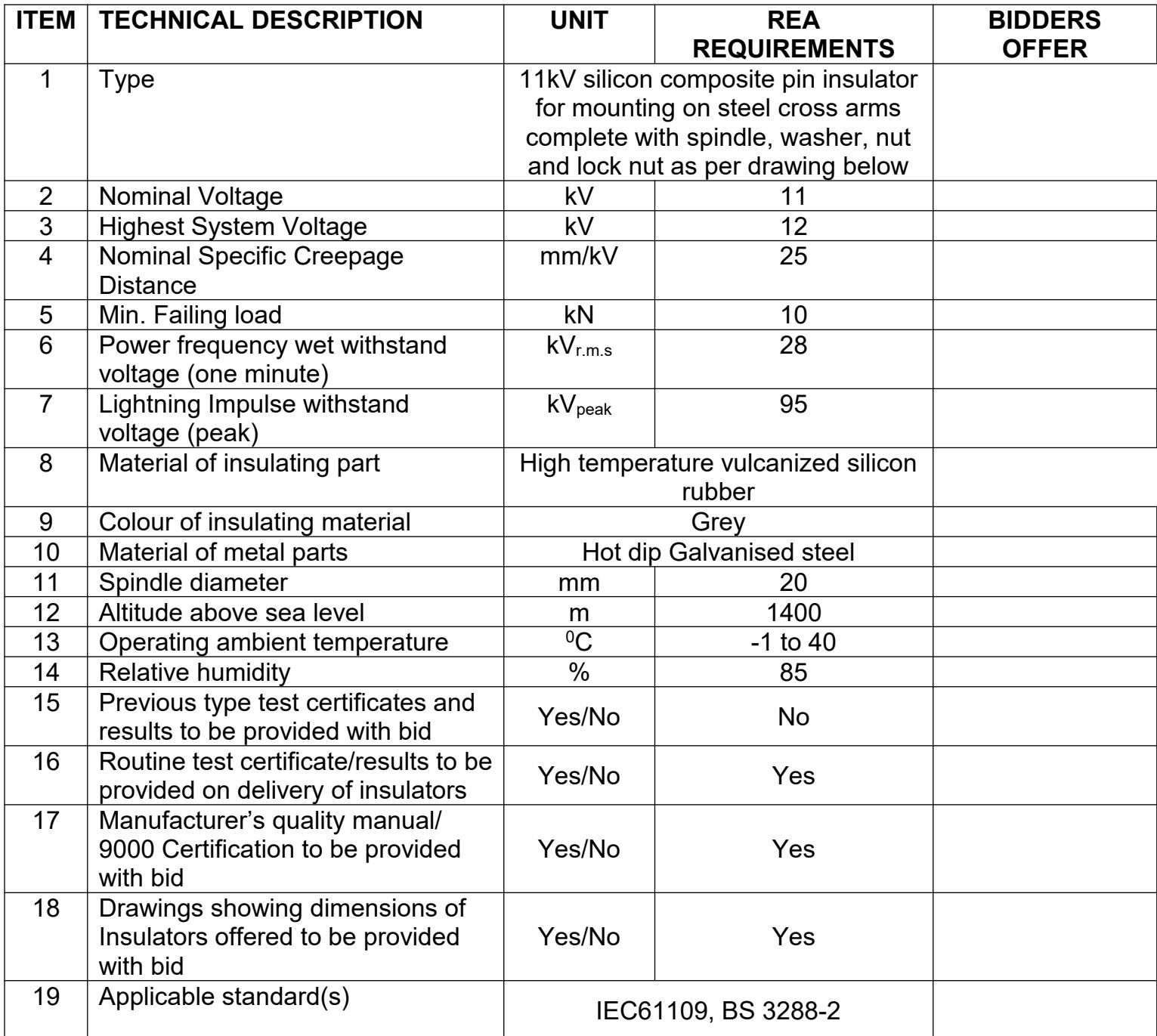
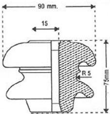
Figure 1.0: 33kV PORCELAIN BROWN/GREY GLAZED PIN INSULATOR DRAWINGS
All dimensions are in mm.

OTHER REQUIREMENTS
Markings
Insulators shall be marked with the specified Electro-mechanical or mechanical failing load e.g. U70 BL.
Insulators shall have indelible manufacturer’s trademark and date of manufacture.
Drawings, Test Certificate/Results and Quality Documents
Tenderer shall provide previous type test certificate/results with bid
Tenderer shall provide routine test results/ certificate on delivery of insulators
Tenderers shall provide drawings showing the dimensions of Insulators offered.
Tenderer shall provide previous 5000 hours ageing test certificate/results according to IEC 61109, with the bid
Special Clause
Tenderers may submit alternative offers which may be of financial or technical benefit to REA
 | TECHNICAL SPECIFICATION | Doc Number:Version: 1 | ||
| CODE: | DESCRIPTION OF MATERIAL: | Page 1 of 2 | ||
| 11kV STRAIN SILLICON (LONG-ROD)INSULATOR | ||||

| ITEM | TECHNICAL DESCRIPTION | UNIT | REA REQUIREMENTS | BIDDER'S OFFER |
| 1 | Type | Strain 11kV Clevis and Tongue high temperature vulcanised silicon rubber insulator to IEC61109 | ||
| 2 | Nominal Voltage | kV | 11 | |
| 3 | Highest System Voltage | kV | 12 | |
| 4 | Required section length of composite insulators (Equivalent to 3-disc insulators with nominal spacing of 146mm) | mm | 292 | |
| 5 | Minimum Lightning Impulse Withstand Voltage | kV | 95 | |
| 6 | Required Minimum Power frequency (1 minute) Withstand Voltage, wet | kV | 28 | |
| 7 | Min failing load (kN)-Mechanical test | kN | 70 | |
| 8 | End fitting design (ball and socket size) as per IEC 60120 | mm | 16 | |
| 9 | Nominal specific creepage Distance | mm/kV | 25 | |
| 10 | Insulating material | High Temperature Vulcanised Silicon rubber | ||
| 11 | Material for the rod | Epoxy resin fibre reinforced | ||
| 12 | End fittings design | Clevis and Tongue, Steel, Hot-Dip Galvanised | ||
| 13 | Altitude above sea level | m | 1400 | |
| 14 | Operating ambient temperature | °C | -1 to 40 | |
| 15 | Relative humidity | % | 85 | |
| 16 | Applicable Standards | IEC 61109 | ||
| 17 | Routine test certificate to be provided on delivery of insulators | Yes/No | Yes | |

| TECHNICAL SPECIFICATION | Doc Number:Version: 1 | ||||
| CODE: | DESCRIPTION OF MATERIAL: | Page 2 of 2 | ||||
| 11kV STRAIN SILLICON (LONG-ROD)INSULATOR | ||||||
| 18 | Previous type test | Type tests certificate/results to be provided with bid | Yes/No | No | ||
| Previous 5000 hours ageing test certificate/results according to IEC 61109 to be provided upon client request. | Yes/No | Yes | ||||
| 19 | Quality Assurance Certification to be provided with bid | Yes/No | Yes | |||
| 20 | Drawings showing dimensions and tolerances of Insulators offered to be provided with bid | Yes/No | Yes | |||
| DRAWING | ||||||

Markings
Insulators shall be marked with the specified Electro-mechanical or mechanical failing load e.g., U70 BL.
Insulators shall have indelible manufacturer’s trademark and date of manufacture.
Special Clause
Tenderers may submit alternative offers which may be of financial or technical benefit to REA.
| TECHNICAL SPECIFICATION | Doc Number:Version: 1 | ||
| CODE: | DESCRIPTION OF MATERIAL: | Page 1 of 3 | ||
| DROP OUT FUSE LINK 11kV ASSEMBLY COMPLETE WITH FUSE CARRIER | ||||

| ITEM | TECHNICAL DESCRIPTION | UNIT | REA REQUIREMENTS | BIDDER'S OFFER | |
| 1 | Description | 11kV Fuse link assembly complete with fuse carrier rated at 100A and NEMA mounting bracket to PIESA 002. | |||
| 2 | System Conditions of service | ||||
| Nominal Voltage (Un) r.m.s | kV | 11 | |||
| Maximum System Voltage (Um) r.m.s | kV | 12 | |||
| Earth | Effective & Non-effective | ||||
| Frequency | Hz | 50 | |||
| 3 | Site Conditions Of Service | ||||
| Altitude | m | 1400 | |||
| Operating Ambient Temperature | °C | -1 to 40 | |||
| Humidity | % | 85 | |||
| 4 | Rating | ||||
| Nominal Voltage | kV | 11 | |||
| Rated Current | Fuse Carrier | A | 100 | ||
| Cut Out Base | A | 200 | |||
| Fuse Element | A | 5 | |||
| 5 | Electrical Conditions | ||||
| Insulation Material Specification | Porcelain | ||||
| Dielectric Strength | |||||
| Lightning Impulse withstand (1.2/50) | kV | 95 | |||
| Power frequency wet withstand voltage r.m.s | kV | 28 | |||
| 6 | Nominal specific Creepage Distance | mm/kV | 25 | ||
| 7 | Creepage Distance | mm | 481 | ||
| 8 | Previous Type test report/certificate on complete fuse link assembly to be provided with bid | Yes/No | No | ||

 | TECHNICAL SPECIFICATION | Doc Number:Version: 1 | ||||
| CODE: | DESCRIPTION OF MATERIAL: | Page 2 of 3 | ||||
| DROP OUT FUSE LINK 11kV ASSEMBLY COMPLETE WITH FUSE CARRIER | ||||||
| 9 | General information to be provided with bid: | |||||
| Drawings and brochures showing outline and general arrangement | Yes/No | Yes | ||||
| Detailed drawings of all items showing critical tolerances to be provided with bid | Yes/No | Yes | ||||
| 10 | Routine tests (acceptance tests on sample Product) to be provided on delivery | Yes/No | Yes | |||
| 11 | Applicable standards | PIESA 002, NRS 035SABS IEC 60282-2SABS IEC 60186BS 137-part 2 | ||||
 | ||||||

MARKING AND IDENTIFICATION
Markings to conform to SABS IEC 60282-2
Insulators shall be marked with the specified Electro-mechanical or mechanical failing load e.g. U70 BL.
Insulators shall have indelible manufacturer’s trademark and date of manufacture.
| TECHNICAL SPECIFICATION | Doc Number:Version: 1 | |||
| CODE: | DESCRIPTION OF MATERIAL: | Page 3 of 3 | ||
| DROP OUT FUSE LINK 11kV ASSEMBLY COMPLETE WITH FUSE CARRIER | ||||

OTHER REQUIREMENTS
There shall be no rivets in the parts that form the current path
Water shall not be able to accumulate on any part of the equipment nor shall any feature introduce moisture into any component.
The design shall incorporate all reasonable precautions and provisions for the safety of personnel concerned with the operation and maintenance of the same.
The current path shall be such that load current shall only flow through high conductive materials such as copper and its alloys. Load current shall not be permitted to flow through ferrous components, springs, or spring-loaded mechanisms.
All load current paths shall be so designed that the relevant parts of the assembly can carry the specified rated current without exceeding the permitted temperature rise in SABS IEC 60282-2
Contacts shall be based on the line contact principle and there shall be no welds on the contact parts. The construction of the Drop out fuse base and the fuse link shall ensure their mutual alignment during closure.
The solid link should have an eye and an operating tongue.
SUPPLIMENTARY NOTES
Suppliers should give sufficient information including drawings (which must be brief, clear and to the point) on how their drop out fuse designs addresses the provided requirements. Suppliers can offer better alternatives that are of cost and technical benefits to the organisations without compromising on the quality.
The drawings to be submitted by the tenderer must:
o Show details of the insulator, the fuse carrier, the solid link, the upper contact, the lower contact, the cut-out base and the bracket for fixing to either wooden or steel cross arm.
o Provided critical tolerances
All tolerances should be as per PIESA 002: 1 2000
Insulator fixing stem galvanized in accordance with SABS 763.
The gusset below the tongue is require for strength, but should not limit the usable length of the torque
The current path, shown only functionally, shall be continuous up to the terminal connector.
Galvanized in accordance with SABS 736
 | TECHNICAL SPECIFICATION | Doc Number:Version: 1 | ||
| CODE: | DESCRIPTION OF MATERIAL: | Page 1 of 1 | ||
| SHACKLE INSULATOR | ||||

| ITEM | TECHNICAL DESCRIPTION | UNIT | REA REQUIREMENTS | BIDDER'S OFFER |
| 1 | Description | Low Voltage Shackle Insulator | ||
| 2 | Nominal system voltage | V | 400 | |
| 3 | System maximum voltage | V | 400 | |
| 4 | Power frequency | Hz | 50 | |
| 5 | Can be used in contamination environment | Yes/No | Yes | |
| 6 | Material | Porcelain | ||
| 7 | Porcelain shall be sound, glazed and smooth | Yes/No | Yes | |
| 8 | Operating Temperature | °C | -1 to 40 | |
| 9 | Altitude above Sea Level | m | 1400 | |
| 10 | Maximum humidity | % | 85 | |
| 11 | Previous Type Tests certificate/results to be provided with bid | Yes/No | No | |
| 12 | Routine Tests Certificates/results to be provided on delivery | Yes/No | Yes | |
| 13 | Quality Assurance Certification to be provided with bid | Yes/No | Yes | |
| 14 | Drawings/brochures submitted with the bid | Yes/No | Yes | |
 | ||||
 | TECHNICAL SPECIFICATION | Doc Number:Version: 1 | ||
| CODE: | DESCRIPTION OF MATERIAL: | Page 1 of 1 | ||
| REEL INSULATOR | ||||

| ITEM | TECHNICAL DESCRIPTION | UNIT | REA REQUIREMENTS | BIDDER'S OFFER |
| 1 | Description | Low Voltage Reel Insulator | ||
| 2 | Nominal system voltage | V | 400 | |
| 3 | System maximum voltage | V | 400 | |
| 4 | Power frequency | Hz | 50 | |
| 5 | Can be used in contamination environment | Yes/No | Yes | |
| 6 | Material | Porcelain | ||
| 7 | Porcelain shall be sound, glazed and smooth | Yes/No | Yes | |
| 8 | Operating Temperature | °C | -1 to 40 | |
| 9 | Altitude above Sea Level | m | 1400 | |
| 10 | Maximum humidity | % | 85 | |
| 11 | Previous Type Tests certificate/results to be provided with bid | Yes/No | No | |
| 12 | Routine Tests Certificates/results to be provided on delivery | Yes/No | Yes | |
| 13 | Quality Assurance Certification to be Provided with Bid | Yes/No | Yes | |
| 14 | Drawings/brochures submitted with the bid | Yes/No | Yes | |
 | ||||

| ITEM | TECHNICAL DESCRIPTION | UNIT | REA REQUIREMENTS | BIDDER'S OFFER | |
| 1 | Description | Porcelain Stay Insulator | |||
| 2 | Leakage Distance | mm | 65 | ||
| 3 | Power Frequency withstand voltage (Wet) | kV | 30 | ||
| 4 | Dry Flash Over | kV | 35 | ||
| 5 | Wet Flash Over | kV | 30 | ||
| 6 | Ultimate Breaking Strength | kN | 70 | ||
| 7 | Can be used in contamination environment | Yes/No | Yes | ||
| 8 | Material | High Grade Glazed Porcelain | |||
| 9 | Porcelain shall be sound, glazed and smooth | Yes/No | Yes | ||
| 10 | Operating Temperature | °C | -1 to 40 | ||
| 11 | Altitude above Sea Level | m | 1400 | ||
| 12 | Maximum humidity | % | 85 | ||
| 13 | Previous Type Tests certificate/results to be provided with bid | Yes/No | No | ||
| 14 | Routine Tests Certificates/results to be provided on delivery | Yes/No | Yes | ||
| 15 | Quality assurance ISO certification to be provided with bid | Yes/No | Yes | ||
| 16 | Drawings/brochures submitted with the bid | Yes/No | Yes | ||
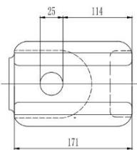  | |||||

 | TECHNICAL SPECIFICATION | Doc Number:Version: 1 | ||
| CODE: | DESCRIPTION OF MATERIAL: | Page 1 of 1 | ||
| STAY PORCELAIN INSULATOR | ||||
| CODE: | DESCRIPTION OF MATERIAL: | Page 1 of 3 | ||
| CABLE MV CU/PVC/PVC/SWA/PVC 4 CORE COPPER 35 MILLIMETRE SQUARED 600/1000V | ||||

| ITEM | TECHNICAL DESCRIPTION | UNIT | REA REQUIREMENTS | BIDDER'S OFFER |
| 1 | Description | 35mm24 coreCU/PVC/PVC/SWA/ PVC600/1000V Cable | ||
| 2 | Conductor Size | mm2 | 5 | |
| 3 | Current Rating (Ground/Air) | A | 143/135 | |
| 4 | Ground Temperature | °C | 25 | |
| 5 | Ground Thermal Resistivity | K.m/W | 1.2 | |
| 6 | Depth of Laying | mm | 800 | |
| 7 | Operating Temperature | °C | -1 to 40 | |
| 8 | Method of Installation | Both in air and direct burial u/g | ||
| 9 | Material of conductor | Stranded Annealed Copper | ||
| 10 | Number of cores | No. | 4 | |
| 11 | Core identification (Phases and Neutral) | Red, Yellow, Blue & Black | ||
| 12 | Rated Voltage ac (Uo/U) | V | 600/1000 | |
| 13 | Highest System Voltage | V | 1100 | |
| 14 | Maximum sustained conductor temperature | °C | 70 | |
| 15 | Single layer steel armour | Yes/No | Yes | |
| 16 | Armour Diameter | As Per PIESA003-1, BS6346 or SANS1507 | ||
| 17 | Packaging/type of drum | Treated wooden | ||
| 18 | Type of Outer Sheath | Ultraviolet stabilize PVC | ||
| 19 | Length per drum | m | 500 | |
| 20 | Possible Exposure to sunlight | Yes/No | Yes | |
| 21 | Insulation material | PVC | ||
| 22 | Bedding material | As per PIESA003-1, BS6346 or SANS1507 | ||
| 23 | Altitude | m | 1400 | |
| 24 | Ambient Air Temperature | °C | 30 | |
| 25 | Relative humidity | % | 85 | |
| TECHNICAL SPECIFICATION | Doc Number:Version: 1 | ||
| CODE: | DESCRIPTION OF MATERIAL: | Page 2 of 3 | ||
| CABLE MV CU/PVC/PVC/SWA/PVC 4 CORE COPPER 35 MILLIMETRE SQUARED 600/1000V | ||||

| 26 | Previous Type Tests Report/Certificate to be provided with bid | Yes/No | No | |
| 27 | Routine Tests Report/Certificates to be provided on delivery | Yes/No | Yes | |
| 28 | Quality Assurance certification to be provided with bid | Yes/No | Yes | |
| 29 | Drawing showing Dimensions and Construction of the Cable to be submitted with bid | Yes/No | Yes | |
| 30 | Applicable Standards | PIESA003-1, BS6346 or SANS1507 | ||

Notes:
Marking
o The external surface of the cable shall be legibly embossed with the following information on two lines running parallel to the length of the cable, approximately equally spaced around the circumference of the cable.
Rural Electrification Authority (REA), Electric Cable 600/1000V Manufacturer’s Name 4x35mm2 CU/PVC/PVC/SWA/PVC
o The bedding material is not included in the CU/PVC/PVC/SWA/PVC naming convention
o In addition, the cable shall be sequentially marked, by indelible printing, indenting or other suitable means, at 1m intervals, to indicate the approximate length of cable remaining on the drum. The numbers shall start with 001, 1m from the inner end of the cable and continue every metre to the outer end. The start and finish lengths of sequential markings (if not 0 to 500m) shall be indicated on the cable drum
o Any material used on the cable should not be hygroscopic.
Suppliers to submit manufacturers’ complete cable technical specification with bid. Values of parameters to be given for both in air and direct buria underground
| TECHNICAL SPECIFICATION | Doc Number:Version: 1 | |
| CODE: | DESCRIPTION OF MATERIAL: | Page 3 of 3 |
| CABLE MV CU/PVC/PVC/SWA/PVC 4 CORE COPPER 35 MILLIMETRE SQUARED 600/1000V |

Fig 1: 4-core 600/1000V Cables with circular or shaped stranded copper conductors, PVC insulation, galvanized steel wire armour and PVC outer sheath.
| 1 Construction area (m2) | 2 Modulation thickness (mm) | 3 Damping thickness (mm) | 4 Diameter of ceramic layer (mm) | 5 Wall sheath thickness (mm) | 6 Approximate (mm OD) |
| Ceramic | |||||
| 4 | 0.9 | 0.8 | 1.25 | 1.5 | 17.8 |
| 6 | 0.9 | 0.8 | 1.28 | 1.8 | 14.2 |
| 10 | 1.0 | 0.9 | 1.26 | 1.8 | 22.8 |
| 16 | 1.0 | 1.0 | 1.0 | 1.7 | 25.3 |
| Magnetic | |||||
| 25 | 1.2 | 1.0 | 1.0 | 1.8 | 27.8 |
| 35 | 1.2 | 1.0 | 1.8 | 1.8 | 30.3 |
| 55 | 1.4 | 1.2 | 2.0 | 2.8 | 35.4 |
| 70 | 1.6 | 1.2 | 2.0 | 2.1 | 36.2 |
| 95 | 1.6 | 1.2 | 2.0 | 2.2 | 36.2 |
| 120 | 1.6 | 1.4 | 2.0 | 2.4 | 43.0 |
| 150 | 1.7 | 1.4 | 2.1 | 2.0 | 53.0 |
| 180 | 2.0 | 1.8 | 2.8 | 2.8 | 59.0 |
| 200 | 2.2 | 1.6 | 2.1 | 2.8 | 65.7 |
| 300 | 2.4 | 1.6 | 2.5 | 2.8 | 71.0 |

| TECHNICAL SPECIFICATION | Doc Number:Version: 1 | ||
| CODE: | DESCRIPTION OF MATERIAL: | Page 1 of 3 | ||
| CABLE MV CU/PVC/PVC/SWA/PVC 4 CORE COPPER70 MILLIMETRE SQUARED 600/1000V | ||||

| ITEM | TECHNICAL DESCRIPTION | UNIT | REA REQUIREMENTS | BIDDER'S OFFER |
| 1 | Description | 70mm2 4 coreCU/PVC/PVC/SWA/ PVC600/1000V Cable | ||
| 2 | Conductor Size | mm2 | 70 | |
| 3 | Current Rating (Ground/Air) | A | 210/207 | |
| 4 | Ground Temperature | °C | 25 | |
| 5 | Ground Thermal Resistivity | K.m/W | 1.2 | |
| 6 | Depth of Laying | mm | 800 | |
| 7 | Operating Temperature | °C | -1 to 40 | |
| 8 | Method of Installation | Both in air and direct burial u/g | ||
| 9 | Material of conductor | Stranded Annealed Copper | ||
| 10 | Number of cores | No. | 4 | |
| 11 | Core identification (Phases and Neutral) | Red, Yellow, Blue & Black | ||
| 12 | Rated Voltage ac (Uo/U) | V | 600/1000 | |
| 13 | Highest System Voltage | V | 1100 | |
| 14 | Maximum sustained conductor temperature | °C | 70 | |
| 15 | Single layer steel armour | Yes/No | Yes | |
| 16 | Armour Diameter | As Per PIESA003-1, BS6346 or SANS1507 | ||
| 17 | Packaging/type of drum | mm | Treated wooden | |
| 18 | Type of Outer Sheath | Ultraviolet stabilize PVC | ||
| 19 | Length per drum | M | 500 | |
| 20 | Possible Exposure to sunlight | Yes/No | Yes | |
| 21 | Insulation material | PVC | ||
| 22 | Bedding material | As per PIESA003-1, BS6346 or SANS1507 | ||
| 23 | Altitude | m | 1400 | |
| 24 | Ambient Air Temperature | °C | 30 | |
| 25 | Relative humidity | % | 85 | |

| TECHNICAL SPECIFICATION | Doc Number:Version: 1 | ||||
| CODE: | DESCRIPTION OF MATERIAL: | Page 2 of 3 | ||||
| CABLE MV CU/PVC/PVC/SWA/PVC 4 CORE COPPER 70 MILLIMETRE SQUARED 600/1000V | ||||||
| 26 | Previous Type Tests Report/Certificate to be provided with bid | Yes/No | No | |||
| 27 | Routine Tests Report/Certificates to be provided on delivery | Yes/No | Yes | |||
| 28 | Quality Assurance certification to be provided with bid | Yes/No | Yes | |||
| 29 | Drawing showing Dimensions and Construction of the Cable to be submitted with bid | Yes/No | Yes | |||
| 30 | Applicable Standards | PIESA003-1, BS6346 or SANS1507 | ||||

Notes:
Marking
o The external surface of the cable shall be legibly embossed with the following information on two lines running parallel to the length of the cable, approximately equally spaced around the circumference of the cable.
Rural Electrification Authority (REA), Electric Cable 600/1000V Manufacturer’s Name 4x70mm2 CU/PVC/PVC/SWA/PVC
o The bedding material is not included in the CU/PVC/PVC/SWA/PVC naming convention
O In addition, the cable shall be sequentially marked, by indelible printing, indenting or other suitable means, at 1m intervals, to indicate the approximate length of cable remaining on the drum. The numbers shall start with 001, 1m from the inner end of the cable and continue every metre to the outer end. The start and finish lengths of sequential markings (if not 0 to 500m) shall be indicated on the cable drum
o Any material used on the cable should not be hygroscopic.
o Suppliers to submit manufacturers’ complete cable technical specification with bid. Values of parameters to be given for both in air and direct burial underground
| TECHNICAL SPECIFICATION | Doc Number:Version: 1 | |||
| CODE: | DESCRIPTION OF MATERIAL: | Page 3 of 3 | ||
| CABLE MV CU/PVC/PVC/SWA/PVC 4 CORE COPPER70 MILLIMETRE SQUARED 600/1000V | ||||

Fig 1: 4-core 600/1000V Cables with circular or shaped stranded copper conductors, PVC insulation, galvanized steel wire armour and PVC outer sheath.

| TECHNICAL SPECIFICATION | Doc Number:Version: 1 | ||
| CODE: | DESCRIPTION OF MATERIAL: | Page 1 of 1 | ||
| INSULATED CONDUCTOR COPPER 70 MILLIMETRE SQUARED | ||||

| ITEM | TECHNICAL DESCRIPTION | UNIT | REA REQUIREMENTS | BIDDER'S OFFER |
| 1 | Description | $70mm^2$ stranded Insulated copper Conductor single core | ||
| 2 | Cross section area | $mm^2$ | 70 | |
| 3 | Rated Voltage ac (Uo/U) | V | 600/1000 | |
| 4 | Highest System Voltage | V | 1100 | |
| 5 | Maximum sustained conductor temperature | $^\circ C$ | 70 | |
| 6 | Colour of Insulation | Green/Yellow | ||
| 7 | Material of Conductor | Annealed hard drawn copper | ||
| 8 | Maximum conductor resistance @ $20^\circ C$ | Ohm/km | 0.25 | |
| 9 | Type | Stranded | ||
| 10 | Insulation Material | PVC | ||
| 11 | Operating Temperature | $^\circ C$ | -1 to 40 | |
| 12 | Altitude above sea level | m | 1400 | |
| 13 | Maximum Humidity | % | 85 | |
| 14 | Packaging/type of drum | Treated wooden drums | ||
| 15 | Possible Exposure to sunlight | Yes/No | Yes | |
| 16 | Previous Type Tests Report/Certificate to be provided upon client request | Yes/No | Yes | |
| 17 | Routine Tests Report/Certificates to be provided on delivery | Yes/No | Yes | |
| 18 | Quality Assurance certification to be provided with bid | Yes/No | Yes | |
| 19 | Drawing showing Dimensions of the Cable to be submitted with bid | Yes/No | Yes | |
| 20 | Applicable Standards | PIESA003-1, BS6346 or SANS1507 | ||
| TECHNICAL SPECIFICATION | Doc Number:Version: 1 | ||
| CODE: | DESCRIPTION OF MATERIAL: | Page 1 of 1 | ||
| CONDUCTOR HDC BARE COPPER 70 MILLIMETRE SQUARED | ||||

| ITEM | TECHNICAL DESCRIPTION | UNIT | REA REQUIREMENTS | BIDDER'S OFFER |
| 1 | Description | 70mm $^2$ stranded bare copper Conductor | ||
| 2 | Cross section area | mm $^2$ | 70 | |
| 3 | Material of Conductor | Annealed hard drawn copper | ||
| 4 | Maximum conductor resistance @ 20°C | Ohm/km | 0.25 | |
| 5 | Type | Stranded | ||
| 6 | Operating Temperature | °C | -1 to 40 | |
| 7 | Altitude above sea level | m | 1400 | |
| 8 | Maximum Humidity | % | 85 | |
| 9 | Packaging/type of drum | Treated wooden drums | ||
| 10 | Previous Type Tests Report/ Certificate to be provided upon client request | Yes/No | Yes | |
| 11 | Routine Tests Report/Certificates to be provided on delivery | Yes/No | Yes | |
| 12 | Quality Assurance certification to be provided with bid | Yes/No | Yes | |
| 13 | Applicable Standards | PIESA003-1, BS6346 or SANS1507 | ||
| TECHNICAL SPECIFICATION | Doc Number:Version: 1 | ||
| CODE: | DESCRIPTION OF MATERIAL: | Page 1 of 1 | ||
| STAY WIRE STRANDED 7/4 MILLIMETRES | ||||

Notes: o Earth-wires are in accordance with the following standards:
| ITEM | TECHNICAL DESCRIPTION | UNIT | REA REQUIREMENTS | BIDDER'S OFFER |
| 1 | Description | 7/4mm Galvanised Steel Stay Wire | ||
| 2 | Material | Galvanised Steel | ||
| 3 | Stranding | No/mm | 7/4 | |
| 4 | Breaking Strength of Wire | kN | 8.534 | |
| 6 | Minimum Breaking Load for conductor | kN | 62.00 | |
| 7 | Operating Temperature | °C | -1 to 40 | |
| 8 | Altitude above sea level | m | 1400 | |
| 9 | Maximum Humidity | % | 85 | |
| 10 | Packaging/type of drum | Treated wooden drums | ||
| 11 | Length per drum | mm | 5000 | |
| 12 | Quality Assurance Certificate to be provided with bid | Yes/No | Yes | |
| 13 | Routine test Report/Certificate to be provided on delivery | Yes/No | Yes | |
| 14 | Applicable Standards | BS 183 | ||
o IEC 888 – Zinc Coated Steel Wires for Stranded Conductors
o IEC 1089 – Round wire concentric lay overhead electrical stranded conductors
o BS 183 – Specification for General Purpose Galvanised Steel Wire Strand
o BS 443 – Galvanised Coating on Wire
| TECHNICAL SPECIFICATION | Doc Number:Version: 1 | ||
| CODE: | DESCRIPTION OF MATERIAL: | Page 1 of 1 | ||
| STAY WIRE/ AERIAL EARTH WIRE STRANDED 7/2.6 MILLIMETRES | ||||

Notes: o Earth-wires are in accordance with the following standards: o IEC 888 – Zinc Coated Steel Wires for Stranded Conductors
| ITEM | TECHNICAL DESCRIPTION | UNIT | REA REQUIREMENTS | BIDDER'S OFFER |
| 1 | Description | 7/2.6mm Galvanised steel earth wire | ||
| 2 | Material | Galvanised Steel | ||
| 3 | Stranding | No/mm | 7/2.6 | |
| 4 | Minimum Breaking Load for conductor | kN | 43.60 | |
| 5 | Nominal Tensile Grade Of the aerial earth wire | Nm/mm $^{2}$ | 1100 | |
| 6 | Operating Temperature | °C | -1 to 40 | |
| 7 | Altitude above sea level | m | 1400 | |
| 8 | Maximum Humidity | % | 85 | |
| 9 | Packaging/type of drum | Treated wooden drums | ||
| 10 | Length per drum | mm | 5000 | |
| 11 | Modulus of elasticity | MPa | 75500 | |
| 12 | Coefficient of linear expansion | mm/C $^{0}$ | 11.5x10 $^{-6}$ | |
| 13 | Nominal mass – Bare | kg/km | 300 | |
| 14 | Quality Assurance Certificate to be provided with bid | Yes/No | Yes | |
| 15 | Routine test Report/Certificate to be provided on delivery | Yes/No | Yes | |
| 16 | Applicable Standards | BS 183 | ||

o IEC 1089 – Round wire concentric lay overhead electrical stranded conductors
o BS 183 – Specification for General Purpose Galvanized Steel Wire Strand
o BS 443 – Galvanized Coating on Wire
| TECHNICAL SPECIFICATION | Doc Number:Version: 1 | ||
| CODE: | DESCRIPTION OF MATERIAL: | Page 1 of 1 | ||
| 400V POLE-MOUNTED CUT-OUT (BS88 J-TYPE FUSES) | ||||

| ITEM | TECHNICAL DESCRIPTION | UNIT | REA REQUIREMENTS | BIDDER'S OFFER |
| 1 | Description | Pole Mounted Low Voltage Fused Cut-Out complete with carrier and 200A fuse | ||
| 2 | Rated Voltage | V | 415 | |
| 3 | Rated Current | A | 400 | |
| 4 | Supply Frequency | Hz | 50 | |
| 5 | Material for Body and Cover | Weather and UV-Resistant PBT (polybutylene terephthalate) and ASA (Acrylic Styrene Acrylonitrile) blended material, Glass filled | ||
| 6 | Material for Phase Busbars | Electro-Tin-Plated Copper | ||
| 7 | Material fir Fuse Wedge Contacts | Brass | ||
| 8 | Material for Cable Sealing Glands | Polyurethane Foam | ||
| 9 | Exposure Rating (cover in place) | IP43 | ||
| 10 | Flammability Rating | UL94 V2, self-extinguishing 30 seconds at 960°C | ||
| 11 | Size of Fixed Studs for Cable Lug | mm | 12 | |
| 12 | Maximum Size of Incoming Cable | $mm^2$ | 300 | |
| 13 | Operating Ambient Temperature | °C | 1-40 | |
| 14 | Relative Humidity | % | 85 | |
| 15 | Altitude | m | 1400 | |
| 16 | Exposure to Sunlight | Yes/No | Yes | |
| Other requirements | ||||
| 17 | Drawings showing dimensions to be provided with the bid | Yes/No | Yes | |
| 18 | Previous Type Tests Report/Certificate to be provided upon client request | Yes/No | Yes | |
| 19 | Routine Tests Report/Certificates to be provided on delivery | Yes/No | Yes | |
| 20 | Applicable standard(s) | BS 7656:1993 (Carrier); BS 88 (Fuse); BS EN 60529 (IP Rating) | ||
  | ||||
| TECHNICAL SPECIFICATION | Doc Number:Version: 1 | ||
| CODE: | DESCRIPTION OF MATERIAL: | Page 1 of 2 | ||
| ARRESTOR LIGHTNING 33kV 10kA LINE TYPE METAL OXIDE GAPLESS | ||||

| ITEM | TECHNICAL DESCRIPTION | UNIT | REA REQUIREMENTS | BIDDER'S OFFER |
| 1 | Type | 33kV Gapless Type Metal Oxide Surge Arrester – Distribution Class | ||
| 2 | Nominal Voltage | kV | 33 | |
| 3 | Highest System Voltage | kV | 36 | |
| 4 | Power frequency | Hz | 50 | |
| 5 | Basic Insulation Level (BIL) | kV | 170 | |
| Ratings and type of surge arrester | ||||
| 6 | Rated voltage of surge arrester | kV | 29 | |
| 7 | Nominal, 8/20 μs, discharge current rating of surge arrester | kA | 10 | |
| 8 | Maximum continuous operating voltage of surge arrester | kV | 22 | |
| 9 | Gapless or gapped type metal-oxide surge arrester | Gapless | ||
| 10 | Insulation Materials | High temperature vulcanised Silicon Rubber | ||
| 11 | Cantilever strength of surge arrester | Nm | 300 | |
| 12 | Rated Frequency of Surge Arrester | Hz | 50 | |
| 13 | Design altitude of surge arrester (above sea level) | m | 1400 | |
| 14 | Design ambient temperature of surge Arrester | °C | -1 to 40 | |
| 15 | Minimum phase-to-ground specific creepage distance of surge arrester | mm/kV | 25 | |
| Automatic earth lead disconnectors requirements | ||||
| 16 | Automatic earth lead disconnectors fitted | Yes/No | Yes | |
| 17 | Is the automatic earth lead disconnector tested in accordance with IEC 60099-4? | Yes/No | Yes | |
| 18 | Corrosion protection of metal and alloy parts: galvanising specification and/or stainless-steel grad. | To SABS 763, 316 | ||

Tenderers may submit alternative offers which may be of financial or technical benefit to REA. Special Clause
| TECHNICAL SPECIFICATION | Doc Number:Version: 1 | ||||
| CODE: | DESCRIPTION OF MATERIAL: | Page 2 of 2 | ||||
| ARRESTOR LIGHTNING 33kV 10kA LINE TYPE METAL OXIDE GAPLESS | ||||||
| 19 | Minimum one-minute wet power frequency withstand voltage of external insulation of surge arrester housing | kV | 70 | |||
| 20 | Maximum steep current impulse residual voltage for a 10 kA, 1/20 μs, discharge current | kV | 99.7 | |||
| 21 | Maximum lightning impulse residual voltage for a 10 kA, 8/20 μs, discharge current | kV | 91.8 | |||
| 22 | Lightning, 1,2/50 μs, impulse withstand level of external insulation of surge arrester housing | kV | 170 | |||
| 23 | Line discharge class rating | Class | 1 | |||
| 24 | Long duration current, 2 000 μs, impulse withstand | A | 250 | |||
| 25 | High current, 4/10 μs, impulse withstand | kA | 100 | |||
| 26 | Previous Type Test reports/certificate to be provided with bid | Yes/No | Yes | |||
| 27 | Routine test results/certificate to be provided on delivery | Yes/No | Yes | |||
| 28 | Drawing showing dimensions of the arrestor to be provided with the bid | Yes/No | Yes | |||
| 29 | Applicable Standards | IEC 60099 | ||||

 | TECHNICAL SPECIFICATION | Doc Number:Version: 1 | ||
| CODE: | DESCRIPTION OF MATERIAL: | Page 1 of 2 | ||
| ARRESTOR LIGHTNING 11kV 10kA LINE TYPE METAL OXIDE GAPLESS | ||||

| ITEM | TECHNICAL DESCRIPTION | UNIT | REA REQUIREMENTS | BIDDER'S OFFER |
| 1 | Type | 11kV gapless type metal oxide surge arrester – Distribution class | ||
| 2 | Nominal Voltage | kV | 11 | |
| 3 | Highest System Voltage | kV | 12 | |
| 4 | Power frequency | Hz | 50 | |
| 5 | Basic Insulation Level (BIL) | kV | 95 | |
| Ratings and type of surge arrester | ||||
| 6 | Rated voltage of surge arrester | kV | 10 | |
| 7 | Nominal, 8/20 μs, discharge current rating of surge arrester | kA | 10 | |
| 8 | Maximum continuous operating voltage of surge arrester | kV | 7.3 | |
| 9 | Gapless or gapped type metal-oxide surge arrester | Gapless | ||
| 10 | Insulation Materials | High temperature vulcanised Silicon Rubber | ||
| 11 | Cantilever strength of surge arrester | Nm | 300 | |
| 12 | Rated Frequency of Surge Arrester | Hz | 50 | |
| 13 | Design altitude of surge arrester (above sea level) | m | 1400 | |
| 14 | Design ambient temperature of surge Arrester | °C | -1 to 40 | |
| 15 | Minimum phase-to-ground specific creepage distance of surge Arrester | mm/kV | 25 | |
| Automatic earth lead disconnectors requirements | ||||
| 16 | Automatic earth lead disconnectors fitted | Yes/No | Yes | |
| 17 | Is the automatic earth lead disconnector tested in accordance with IEC 60099-4? | Yes/No | Yes | |
| 18 | Corrosion protection of metal and alloy parts: galvanising specification and/or stainless-steel grad. | To SABS 763, 316 | ||

| TECHNICAL SPECIFICATION | Doc Number:Version: 1 | ||||
| CODE: | DESCRIPTION OF MATERIAL: | Page 2 of 2 | ||||
| ARRESTOR LIGHTNING 11kV 10kA LINE TYPE METAL OXIDE GAPLESS | ||||||
| 19 | Minimum one-minute wet power frequency withstand voltage of external insulation of surge arrester housing | kV | 28 | |||
| 20 | Maximum steep current impulse residual voltage for a 10 kA, 1/20 μs, discharge current | kV | 50 | |||
| 21 | Maximum lightning impulse residual voltage for a 10 kA, 8/20 μs, discharge current | kV | 40 | |||
| 22 | Lightning, 1,2/50 μs, impulse withstand level of external insulation of surge arrester housing | kV | 95 | |||
| 23 | Line discharge class rating | Class | 1 | |||
| 24 | Long duration current, 2 000 μs, impulse withstand | A | 250 | |||
| 25 | High current, 4/10 μs, impulse withstand | kA | 100 | |||
| 26 | Previous Type Test Report/Certificate to be provided with bid | Yes/No | Yes | |||
| 27 | Routine test Report/Certificate to be provided on delivery | Yes/No | Yes | |||
| 28 | Drawing showing dimensions of the arrestor to be provided with the bid | Yes/No | Yes | |||
| 29 | Applicable Standards | IEC 60099, SABS 763, 316 | ||||

Tenderers may submit alternative offers which may be of financial or technical benefit to REA.
Special Clause
 | TECHNICAL SPECIFICATION | Doc Number:Version: 1 |
| CODE: | DESCRIPTION OF MATERIAL: | Page 1 of 3 |
| STAY ASSEMBLY 2.5 METRES COMPLETE WITH BASE PLATE, 3 GUY GRIPS AND 1 TOP MAKE-OFF |

| ITEM | TECHNICAL DESCRIPTION | UNIT | REA REQUIREMENTS | BIDDER'S OFFER |
| 1 | Description | Adjustable Stay assembly complete with stay rod, bow, thimble, base plate, 3 Guy Grips and 1 top make-off | ||
| 2 | Material | Mild steel, Hot Dip Galvanised | ||
| 3 | Grade of Steel | 300W | ||
| 4 | Corrosion protection | Galvanised to SABS 763 | ||
| 6 | Base Plate Dimensions | mm | 450 x 450 x 6mm | |
| 7 | Stay Rod Dimensions | M20x2.5m | ||
| 8 | Thimble | To take 7/4mm stay wire | ||
| 9 | Minimum ultimate tensile strength of complete stay assembly | kN | 34 | |
| 10 | Ambient operating temperature | oC | -1 to 40 | |
| 11 | Minimum Humidity | % | 85 | |
| 12 | Previous type test certificate/results/reports to be provide upon client request | Yes/No | Yes | |
| 13 | Detailed drawings of stay rod, anchor rod type, stay base plate and thimble to be provided with the bid | Yes/No | Yes | |
| 14 | Quality assurance certificate/manuals to be provided with the bid. | Yes/No | Yes | |
| 15 | Route test results/certificate to be provide on delivery | Yes/No | Yes | |
| 16 | Applicable standard | PIESA 1007 | ||

| TECHNICAL SPECIFICATION | Doc Number:Version: 1 | |
| CODE: | DESCRIPTION OF MATERIAL: | Page 2 of 3 |
| STAY ASSEMBLY 2.5 METRES COMPLETE WITH BASE PLATE, 3 GUY GRIPS AND 1 TOP MAKE-OFF |

Notes:
O The guy grips and top make off shall be suitable for use with stay strand (stay wire) to BS 183 and of the following characteristics.
o Size of stay wire: 7/4mm SWG
o Minimum Breaking Load of stay wire: 62KN
o The guy grip and top make off shall be manufactured from galvanized steel wire of such quality that when applied to the specified stay wire, they hold full rated breaking strength of the stay wire.
o The guy grips and top make off shall be capable of being removed and reapplied to their original position on the stay wire up to three (3) times for the purpose of stay adjustment during line construction procedures.
o Stay wires are in accordance with the following standards:
o IEC 888 – Zinc Coated Steel Wires for Stranded Conductors
o IEC 1089 – Round wire concentric lay overhead electrical stranded conductors
o BS 183 – Specification for General Purpose Galvanised Steel Wire Strand
o BS 443 – Galvanised Coating on Wire
DRAWINGS
1. Stay Assembly

| No. | Description | Material | QTY |
| 1 | Stay thimble | Hot Digged galvanized Steel | 1 |
| 2 | eye bolt | Hot Dipped galvanized Steel | 1 |
| 3 | Nut | Hot Dipped galvanized Steel | 4 |
| 4 | Tube | Hot Dipped galvanized Steel | 1 |
| 5 | Rad | Hot Dipped galvanized Steel | 1 |
| 6 | Stay plate | Hot Digged galvanized Steel | 1 |

 | TECHNICAL SPECIFICATION | Doc Number:Version: 1 |
| CODE: | DESCRIPTION OF MATERIAL: | Page 3 of 3 |
| STAY ASSEMBLY 2.5 METRES COMPLETE WITH BASE PLATE, 3 GUY GRIPS AND 1 TOP MAKE-OFF |

2. Guy Grip

3. Pole Top Make-off

| TECHNICAL SPECIFICATION | Doc Number:Version: 1 | ||
| CODE: | DESCRIPTION OF MATERIAL: | Page 1 of 1 | ||
| BARBED WIRE – TRADITIONAL TWIST | ||||

| ITEM | TECHNICAL DESCRIPTION | UNIT | REA REQUIREMENTS | BIDDER'S OFFER |
| 1 | Description | Barbed Wire | ||
| 2 | Wire type | Two twisted | ||
| 3 | Number of spikes | No. | 4 | |
| 4 | Spikes space at distance | mm | 75 – 100 | |
| 5 | Horizontal wire barbed wire diameter | mm | 1.7mm – 2.5mm | |
| 6 | Spike wire diameter | mm | 1.5mm – 2.0mm | |
| 7 | Strength of horizontal line wire | N/mm $^{2}$ | 1150 | |
| 8 | Strength of barb wire | N/mm $^{2}$ | 700/ 900 | |
| 9 | Stranded wire breaking load | N(min) | 4230 | |
| 10 | Material treatment | Steel (Hot dipped galvanized) | ||
| 11 | Barb length | mm | 16 | |
| TECHNICAL SPECIFICATION | Doc Number:Version: 1 | ||
| CODE: | DESCRIPTION OF MATERIAL: | Page 1 of 1 | ||
| SUSPENSION CLAMP | ||||

| ITEM | TECHNICAL DESCRIPTION | UNIT | REA REQUIREMENTS | BIDDER'S OFFER | ||
| 1 | Description | Suspension Clamp | ||||
| 2 | Minimum Failing Load | kN | 70 | |||
| 3 | Material for Body | Aluminum Alloy | ||||
| 4 | Material for Bolts & Nuts | Grade 8.8, Hot-Dip Galvanised Steel | ||||
| 5 | Material for Pin | Stainless Steel | ||||
| 6 | Applicable to Conductor Size (ACSR) | $mm^2$ | 100 | |||
| 7 | Quality Assurance Certificate | Yes/No | Yes | |||
| 8 | Operating Ambient Temperature | °C | 1-40 | |||
| 9 | Relative Humidity | % | 85 | |||
| 10 | Altitude | m | 1400 | |||
| Drawing |  | |||||
| TECHNICAL SPECIFICATION | Doc Number:Version: 1 | ||||
| CODE: | DESCRIPTION OF MATERIAL: | Page 1 of 1 | ||||
| D-SHACKLE | ||||||

| ITEM | TECHNICAL DESCRIPTION | UNIT | REA REQUIREMENTS | BIDDER'S OFFER | ||||
| 1 | Description | D-Shackle | ||||||
| 2 | Minimum Failing Load | kN | 70 | |||||
| 3 | Material for Body | Grade 8.8, Hot-Dip Galvanised Steel | ||||||
| 4 | Material for Bolts & Nuts | Grade 8.8, Hot-Dip Galvanised Steel | ||||||
| 5 | Material for Pin | Stainless Steel | ||||||
| 6 | Quality Assurance Certificate | Yes/No | Yes | |||||
| 7 | Operating Ambient Temperature | °C | 1-40 | |||||
| 8 | Relative Humidity | % | 85 | |||||
| 9 | Altitude | m | 1400 | |||||
| Drawing | NOTE:D≥8mm, L≥33mm, F≥7.5mm, d≥17mm, B≥17mm | |||||||
| TECHNICAL SPECIFICATION | Doc Number:Version: 1 | ||||||
| CODE: | DESCRIPTION OF MATERIAL: | Page 1 of 1 | ||||||
| LOW VOLTAGE D-IRON | ||||||||
| ITEM | TECHNICAL DESCRIPTION | UNIT | REA REQUIREMENTS | BIDDER'S OFFER | ||||
| 1 | Description | Low voltage D-Iron | ||||||
| 2 | Nominal system voltage | V | 400 | |||||
| 3 | System maximum voltage | V | 400 | |||||
| 4 | Power frequency | Hz | 50 | |||||
| 5 | Temperature range | °C | -40°C to +40°C | |||||
| 6 | Failing load | % | 85 | |||||
| 7 | Minimum flashover voltage power frequency dry | kV | 16 | |||||
| 8 | Minimum flashover voltage power frequency wet | kV | 7 | |||||
| 9 | Weight | kg | 0 | |||||
| 10 | Material | Steel (Hot dipped galvanized) | ||||||
| 11 | Quality Assurance Certification to be provided with bid | Yes/No | Yes | |||||
| 12 | Drawings/brochures submitted with the bid | Yes/No | Yes | |||||
  | ||||||||
| WOODEN POLE STAPLE | ||||||||

| ITEM | TECHNICAL DESCRIPTION | UNIT | REA REQUIREMENTS | BIDDER'S OFFER |
| 1 | Description | Hot Dip Galvanized Diamond Point Staples | ||
| 2 | Wire Dia. (C) | mm | 4 | |
| 3 | Overall Length (A) | mm | 50 | |
| 4 | Inside Spread (B) | mm | 12 | |
| 5 | Material | Steel (Hot-Dip Galvanized) | ||
6 | DrawingTECHNICAL SPECIFICATION | CUT POINTDoc Number:Version: 1 | ||
| CODE: | DESCRIPTION OF MATERIAL: | Page 1 of 1 | ||
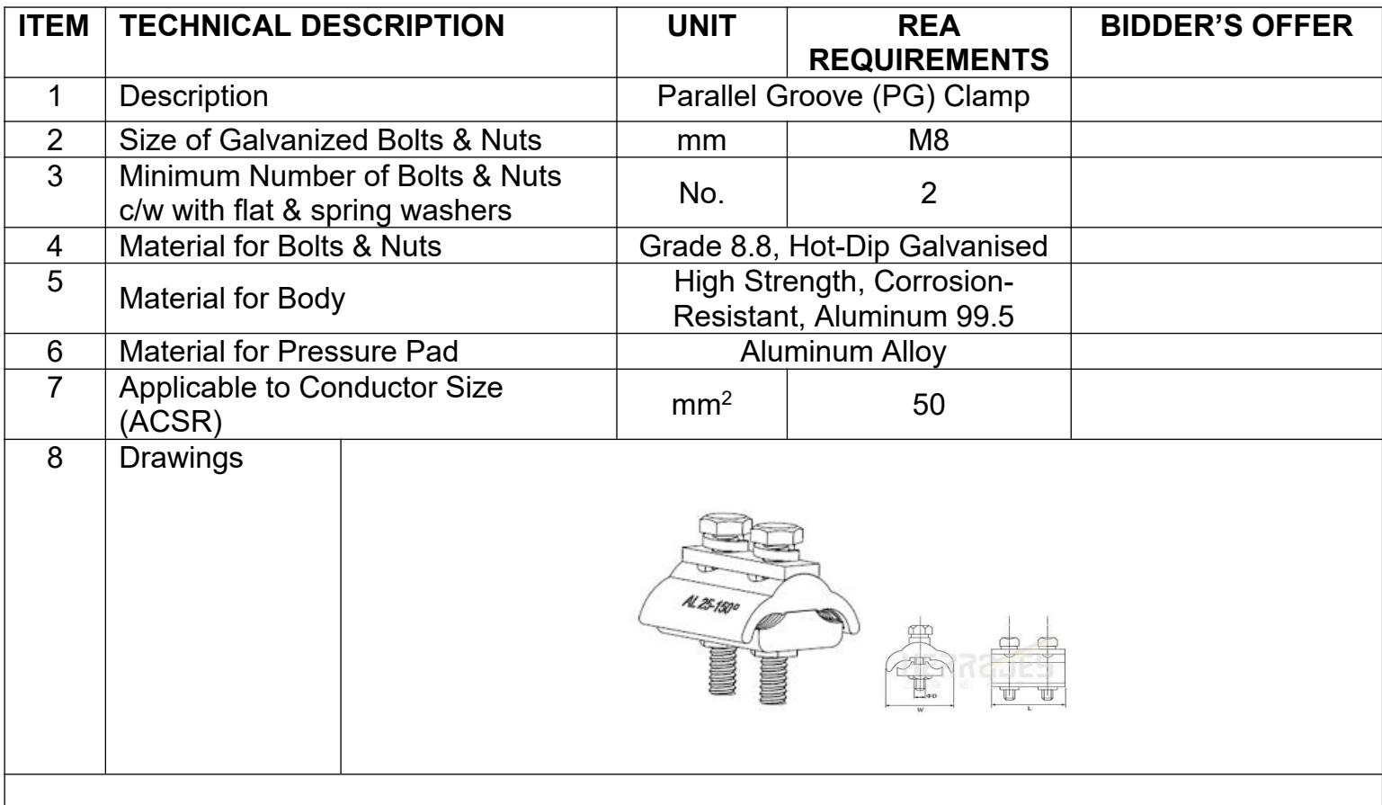
| PARALLEL GROOVE (PG) CLAMP 50 MILLIMETRE SQUARED | ||||

| ITEM | TECHNICAL DESCRIPTION | UNIT | REA REQUIREMENTS | BIDDER'S OFFER | |
| 1 | Description | Parallel Groove (PG) Clamp | |||
| 2 | Size of Galvanized Bolts & Nuts | mm | M8 | ||
| 3 | Minimum Number of Bolts & Nuts c/w with flat & spring washers | No. | 2 | ||
| 4 | Material for Bolts & Nuts | Grade 8.8, Hot-Dip Galvanised | |||
| 5 | Material for Body | High Strength, Corrosion-Resistant, Aluminum 99.5 | |||
| 6 | Material for Pressure Pad | Aluminum Alloy | |||
| 7 | Applicable to Conductor Size (ACSR) | $mm^2$ | 50 | ||
| 8 | DrawingsTECHNICAL SPECIFICATION | Doc Number:Version: 1  | |||
| CODE: | DESCRIPTION OF MATERIAL: | Page 1 of 1 | |||
| PARALLEL GROOVE (PG) CLAMP 100 MILLIMETRE SQUARED | |||||
| ITEM | TECHNICAL DESCRIPTION | UNIT | REA REQUIREMENTS | BIDDER'S OFFER | |
| 1 | Description | Parallel Groove (PG) Clamp | |||
| 2 | Size of Galvanized Bolts & Nuts | mm | M8 | ||
| 3 | Minimum Number of Bolts & Nuts c/w with flat & spring washers | No. | 2 | ||
| 4 | Material for Bolts & Nuts | Grade 8.8, Hot-Dip Galvanised | |||
| 5 | Material for Body | High Strength, Corrosion-Resistant, Aluminum 99.5 | |||
| 6 | Material for Pressure Pad | Aluminum Alloy | |||
| 7 | Applicable to Conductor Size (ACSR) | $mm^2$ | 100 | ||
8 | DrawingsTECHNICAL SPECIFICATION | Doc Number:Version: 1  | |||
| CODE: | DESCRIPTION OF MATERIAL: | Page 1 of 2 | |||
| 35MM X 16MM CABLE LUG, | |||||

| ITEM | TECHNICAL DESCRIPTION | UNIT | REA REQUIREMENTS | BIDDER'S OFFER |
| 1 | Description | Mechanical Connector, Tinned Copper Cable Lug, 35/16mm | ||
| 2 | Conductor Size | $mm^2$ | 35 | |
| 3 | Palm Hole Size | mm | To take M16 Bolt | |
| 4 | Maximum System Voltage | kV | 36 | |
| 5 | Material | Tinned Copper | ||
| 6 | Class | A | ||
| 7 | Markings | As per Manufacturer's mark and serial number, conductor range, palm hole size | ||
| 8 | Grooved internal surface of conductor hole | Yes/No | Yes | |
| 9 | Lengthwise striated inserts for at least16mm2 conductor to be provided | Yes/No | Yes | |
| 10 | Operating Ambient Temperature | °C | 1-40 | |
| 11 | Relative Humidity | % | 85 | |
| 12 | Altitude | m | 1400 | |
| 13 | Exposure to Sunlight | Yes/No | Yes | |
| 14 | Quality Assurance Certification to be provided with bid | Yes/No | Yes | |
| 17 | Applicable standard(s) | BS 4579 or Equivalent | ||
 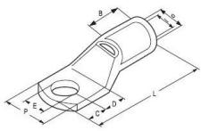 | ||||
| TECHNICAL SPECIFICATION | Doc Number:Version: 1 | ||
| CODE: | DESCRIPTION OF MATERIAL: | Page 1 of 1 | ||
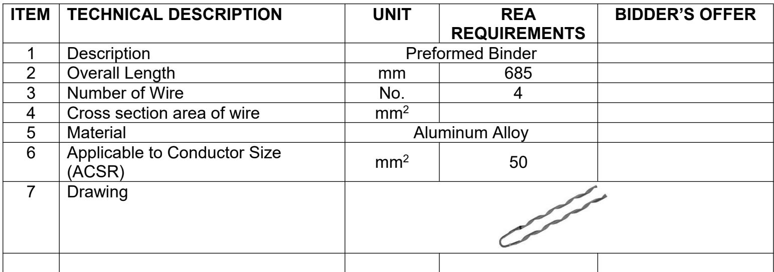
| PREFORMED BIDDERS | ||||

| ITEM | TECHNICAL DESCRIPTION | UNIT | REA REQUIREMENTS | BIDDER'S OFFER |
| 1 | Description | Preformed Binder | ||
| 2 | Overall Length | mm | 685 | |
| 3 | Number of Wire | No. | 4 | |
| 4 | Cross section area of wire | $mm^2$ | ||
| 5 | Material | Aluminum Alloy | ||
| 6 | Applicable to Conductor Size (ACSR) | $mm^2$ | 50 | |
| 7 | Drawing | |||
 | TECHNICAL SPECIFICATION | Doc Number:Version: 1 | |
| CODE: | DESCRIPTION OF MATERIAL: | Page 1 of 1 | |
| COPPER CLAD STEEL EARTH ROD | |||

| ITEM | TECHNICAL DESCRIPTION | UNIT | REA REQUIREMENTS | BIDDER'S OFFER |
| 1 | Description | Copper Clad Steel Earth Rod c/w Rod to Cable Clamp | ||
| 2 | Type | Threaded M16x2 | ||
| 3 | Material | Copper | ||
| 4 | Purity of Copper | % | 99.9 | |
| 5 | Steel Tensile Strength | MPa | 550-700 | |
| 6 | Thickness of Copper | mm | 0.254 | |
| 7 | Rod Diameter | mm | 16 | |
| 8 | Length | m | 2.5 | |
| 9 | Grade | Oxygen Free, ETP, Phosphorised | ||
| 10 | Ends | Chamfered and Pointed | ||
| 11 | Quality Assurance Certification to be provided with bid | Yes/No | Yes | |
| 12 | Drawings/brochures submitted with the bid | Yes/No | Yes | |
DRAWINGNOTE:L=2400mm 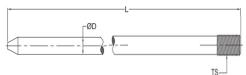 | ||||
| TECHNICAL SPECIFICATION | Doc Number:Version: 1 | ||
| CODE: | DESCRIPTION OF MATERIAL: | Page 1 of 1 | ||
| BRASS LINE TAP 100MILLIMETRE | ||||

| ITEM | TECHNICAL DESCRIPTION | UNIT | REA REQUIREMENTS | BIDDER'S OFFER | |
| 1 | Description | $100mm^{2}$ Brass line tap | |||
| 2 | Conductor cross section area | mm | 100 | ||
| 3 | Material | Brass As Per BS 249 | |||
| 4 | Corrosion protection | Tin platted | |||
| 5 | Dimensions | As per Drawing below | |||
| Other requirements | |||||
| 6 | Drawings showing dimensions to be provided with the bid | Yes/No | Yes | ||
| 7 | Quality Assurance certification to be provided with bid | Yes/No | Yes | ||
| 8 | Applicable standard(s) | IEC Standards | |||
| 9 | DrawingTECHNICAL SPECIFICATION | Doc Number:Version: 1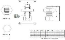 | |||
| CODE: | DESCRIPTION OF MATERIAL: | Page 1 of 1 | |||
| BRASS LINE TAP 50MILLIMETRE | |||||

| ITEM | TECHNICAL DESCRIPTION | UNIT | REA REQUIREMENTS | BIDDER'S OFFER | |
| 1 | Description | 50mm $^2$ Brass line tap | |||
| 2 | Conductor cross section area | mm | 50 | ||
| 3 | Material | Brass As Per BS 249 | |||
| 4 | Corrosion protection | Tin platted | |||
| 5 | Dimensions | As per Drawing below | |||
| Other requirements | |||||
| 6 | Drawings showing dimensions to be provided with the bid | Yes/No | Yes | ||
| 7 | Quality Assurance certification to be provided with bid | Yes/No | Yes | ||
| 8 | Applicable standard(s) | IEC Standards | |||
| 9 | DrawingTECHNICAL SPECIFICATION | Doc Number:Version: 1 | |||
| CODE: | DESCRIPTION OF MATERIAL: | Page 1 of 2 | |||
| GALVANISED STEEL CROSSARMS 33kV AERIALEARTH 70x70x8x2100 MILLIMETRES | |||||

| ITEM | TECHNICAL DESCRIPTION | UNIT | REA REQUIREMENTS | BIDDER'S OFFER |
| 1 | Description | 33kV Aerial Earth Galvanized Steel Crossarm (70x70x8x2100mm) | ||
| 2 | Channel Height (A) | mm | 70 | |
| Flange Width (B) | mm | 70 | ||
| 3 | Web Thickness (C) | mm | 8 | |
| 4 | Overall Length | mm | 2100 | |
| 5 | Material | Hot dip galvanized Steel as per ISO1461 | ||
| 6 | Grade of Steel | S355 | ||
| 7 | Position of Holes | As per provided detailed drawing on next page | ||
| Other requirements | ||||
| 8 | Drawings showing dimensions to be provided with the bid | Yes/No | Yes | |
| 9 | Previous type test of steel to be provided upon client request | Yes/No | Yes | |
| 10 | Quality assurance certificate to be provided with the bid | Yes/No | Yes | |
| 11 | Applicable standard(s) | IEC Standards | ||
| 12 | DrawingTECHNICAL SPECIFICATION | Doc Number:Version: 1 | ||
| CODE: | DESCRIPTION OF MATERIAL: | Page 2 of 2 | ||
| GALVANISED STEEL CROSSARMS 33kV AERIALEARTH 70x70x8x2100 MILLIMETRES | ||||


| TECHNICAL SPECIFICATION | Doc Number:Version: 1 | ||
| CODE: | DESCRIPTION OF MATERIAL: | Page 1 of 2 | ||
| GALVANISED STEEL CROSSARMS 11kV MAIN70x50x6x2700 MILLIMETRES | ||||

| ITEM | TECHNICAL DESCRIPTION | UNIT | REA REQUIREMENTS | BIDDER'S OFFER |
| 1 | Description | 11kV Main Galvanized Steel Crossarm (70x50x6x2700mm) | ||
| 2 | Channel Height (A) | mm | 70 | |
| Flange Width (B) | mm | 50 | ||
| 3 | Web Thickness (C) | mm | 6 | |
| 4 | Overall Length | mm | 2700 | |
| 5 | Material | Hot dip galvanized Steel as per ISO1461 | ||
| 6 | Grade of Steel | S355 | ||
| 7 | Position of Holes | As per provided detailed drawing on next page | ||
| Other requirements | ||||
| 8 | Drawings showing dimensions to be provided with the bid | Yes/No | Yes | |
| 9 | Previous type test of steel to be provided upon client request | Yes/No | Yes | |
| 10 | Quality assurance certificate to be provided with the bid | Yes/No | Yes | |
| 11 | Applicable standard(s) | IEC Standards | ||
12 | DrawingTECHNICAL SPECIFICATION | Doc Number:Version: 1 | ||
| CODE: | DESCRIPTION OF MATERIAL: | Page 2 of 2 | ||
| GALVANISED STEEL CROSSARMS 11kV MAIN70x50x6x2700 MILLIMETRES | ||||


| TECHNICAL SPECIFICATION | Doc Number:Version: 1 | ||
| CODE: | DESCRIPTION OF MATERIAL: | Page 1 of 2 | ||
| GALVANISED STEEL CROSSARMS 33kV MAIN180x70x8x4100 MILLIMETRES | ||||

| ITEM | TECHNICAL DESCRIPTION | UNIT | REA REQUIREMENTS | BIDDER'S OFFER |
| 1 | Description | 33kV Main Galvanized Steel Crossarm (180x70x8x4100mm) | ||
| 2 | Channel Height (A) | mm | 180 | |
| Flange Width (B) | mm | 70 | ||
| 3 | Web Thickness (C) | mm | 8 | |
| 4 | Overall Length | mm | 4100 | |
| 5 | Material | Hot dip galvanized Steel as per ISO1461 | ||
| 6 | Grade of Steel | S355 | ||
| 7 | Position of Holes | As per provided detailed drawing on next page | ||
| Other requirements | ||||
| 8 | Drawings showing dimensions to be provided with the bid | Yes/No | Yes | |
| 9 | Previous type test of steel to be provided upon client request | Yes/No | Yes | |
| 10 | Quality assurance certificate to be provided with the bid | Yes/No | Yes | |
| 11 | Applicable standard(s) | IEC Standards | ||
| 12 | DrawingTECHNICAL SPECIFICATION | Doc Number:Version: 1 | ||
| CODE: | DESCRIPTION OF MATERIAL: | Page 2 of 2 | ||
| GALVANISED STEEL CROSSARMS 33kV MAIN180x70x8x4100 MILLIMETRES | ||||


| TECHNICAL SPECIFICATION | Doc Number:Version: 1 | ||
| CODE: | DESCRIPTION OF MATERIAL: | Page 1 of 2 | ||
| GALVANISED STEEL CROSSARMS 11kV DROP-OUT FUSE 70x60x6x2700 MILLIMETRES | ||||

| ITEM | TECHNICAL DESCRIPTION | UNIT | REA REQUIREMENTS | BIDDER'S OFFER |
| 1 | Description | 11kV Drop-Out Fuse/Solid Link Galvanized Steel Crossarm (70x60x6x2700mm) | ||
| 2 | Channel Height (A) | mm | 70 | |
| Flange Width (B) | mm | 60 | ||
| 3 | Web Thickness (C) | mm | 6 | |
| 4 | Overall Length | mm | 2700 | |
| 5 | Material | Hot dip galvanized Steel as per ISO1461 | ||
| 6 | Grade of Steel | S355 | ||
| 7 | Position of Holes | As per provided detailed drawing on next page | ||
| Other requirements | ||||
| 8 | Drawings showing dimensions and position of holes to be provided with the bid | Yes/No | Yes | |
| 9 | Previous type test Report/Certificate for the steel to be provided upon client request | Yes/No | Yes | |
| 10 | Quality Assurance ISO certification to be provided with bid | Yes/No | Yes | |
| 11 | Applicable standard(s) | IEC Standards | ||
| 12 | DrawingTECHNICAL SPECIFICATION | Doc Number:Version: 1 | ||
| CODE: | DESCRIPTION OF MATERIAL: | Page 2 of 2 | ||
| GALVANISED STEEL CROSSARMS 11kV DROP-OUT FUSE 70x60x6x2700 MILLIMETRES | ||||


| TECHNICAL SPECIFICATION | Doc Number:Version: 1 | ||
| CODE: | DESCRIPTION OF MATERIAL: | Page 1 of 2 | ||
| GALVANISED STEEL CROSSARMS 33kV DROP-OUT FUSE 150x75x8x4100 MILLIMETRES | ||||

| ITEM | TECHNICAL DESCRIPTION | UNIT | REA REQUIREMENTS | BIDDER'S OFFER |
| 1 | Description | 33kV Drop-Out Fuse/Solid Link Galvanized Steel Crossarm (150x75x8x4100mm) | ||
| 2 | Channel Height (A) | mm | 150 | |
| Flange Width (B) | mm | 75 | ||
| 3 | Web Thickness (C) | mm | 8 | |
| 4 | Overall Length | mm | 4100 | |
| 5 | Material | Hot dip galvanized Steel as per ISO1461 | ||
| 6 | Grade of Steel | S355 | ||
| 7 | Position of Holes | As per provided detailed drawing on next page | ||
| Other requirements | ||||
| 8 | Drawings showing dimensions to be provided with the bid | Yes/No | Yes | |
| 9 | Previous type test of steel to be provided upon client request | Yes/No | Yes | |
| 10 | Quality assurance certificate to be provided with the bid | Yes/No | Yes | |
| 11 | Applicable standard(s) | IEC Standards | ||
| 12 | DrawingTECHNICAL SPECIFICATION | Doc Number:Version: 1 | ||
| CODE: | DESCRIPTION OF MATERIAL: | Page 2 of 2 | ||
| GALVANISED STEEL CROSSARMS 33kV DROP-OUT FUSE 150x75x8x4100 MILLIMETRES | ||||


 | TECHNICAL SPECIFICATION | Doc Number:Version: 1 | ||
| CODE: | DESCRIPTION OF MATERIAL: | Page 1 of 2 | ||
| GALVANISED STEEL CROSSARMS TRANSFORMPLATFORM 100x50x6x2100 MILLIMETRES | ||||

| ITEM | TECHNICAL DESCRIPTION | UNIT | REA REQUIREMENTS | BIDDER'S OFFER |
| 1 | Description | Transformer Platform Galvanized Steel Crossarm (100x50x6x2100mm) | ||
| 2 | Channel Height (A) | mm | 100 | |
| Flange Width (B) | mm | 50 | ||
| 3 | Web Thickness (C) | mm | 6 | |
| 4 | Overall Length | mm | 2100 | |
| 5 | Material | Hot dip galvanized Steel as per ISO1461 | ||
| 6 | Grade of Steel | S355 | ||
| 7 | Position of Holes | As per provided detailed drawing on next page | ||
| Other requirements | ||||
| 8 | Drawings showing dimensions to be provided with the bid | Yes/No | Yes | |
| 9 | Previous type test of steel to be provided upon client request | Yes/No | Yes | |
| 10 | Quality Assurance Certification to be provided with bid | Yes/No | Yes | |
| 11 | Applicable standard(s) | IEC Standards | ||
| 12 | DrawingTECHNICAL SPECIFICATION | Doc Number:Version: 1 | ||
| CODE: | DESCRIPTION OF MATERIAL: | Page 2 of 2 | ||
| GALVANISED STEEL CROSSARMS TRANSFORMPLATFORM 100x50x6x2100 MILLIMETRES | ||||


 | TECHNICAL SPECIFICATION | Doc Number:Version: 1 | ||
| CODE: | DESCRIPTION OF MATERIAL: | Page 1 of 2 | ||
| SUSPENSION CLAMP FOR AERIAL BUNDLED CABLE (ABC) 25-95 MILLIMETRE | ||||

| ITEM | TECHNICAL DESCRIPTION | UNIT | REA REQUIREMENTS | BIDDER'S OFFER | |
| 1 | Description | Suspension Clamp for Aerial Bundled Cable (ABC) 16-35mm | |||
| 2 | Rated Voltage | kV | 0.6 | ||
| 3 | Minimum Breaking Load | kN | 4.5 | ||
| 4 | Number of Cores | No. | 01 | ||
| 5 | Applicable to Conductor Size | mm | 25-95 | ||
| 6 | Materials for Non-Metallic parts of Fitting | Ultraviolet stabilized and fire retardant materials | |||
| 7 | Materials for Ferrous parts of fitting | Hot Dip Galvanized | |||
| 8 | Colour of Fitting Insulating Parts | Black | |||
| 9 | Operating Ambient Temperature | °C | 1-40 | ||
| 10 | Relative Humidity | % | 85 | ||
| 11 | Altitude | m | 1400 | ||
| 12 | Previous type Tests results/certificate to be provided upon client request: | Dielectric of fitting mounted on cable | Yes/No | Yes | |
| Accelerated weathering test | Yes/No | Yes | |||
| Tensile Test | Yes/No | Yes | |||
| 13 | Drawings showing design details to be provided with the bid | Yes/No | Yes | ||
| 14 | Quality assurance certificate to be provided with the bid | Yes/No | Yes | ||
| 15 | Routine tests to be provided on delivery | Yes/No | Yes | ||
| 16 | Applicable Standards | PIESA 1018-4 | |||


| TECHNICAL SPECIFICATION | Doc Number:Version: 1 | |||
| CODE: | DESCRIPTION OF MATERIAL: | Page 2 of 2 | ||
| SUSPENSION CLAMP FOR AERIAL BUNDLEDCABLE (ABC) 25-95 MILLIMETRE | ||||

NOTES:
The clamp shall be designed to hang LV–ABC cable with insulated neutral conductor. The neutral conductor shall be fixed by an adjustable grip device. A movable link shall allow longitudinal and transversal movement of the clamp body.
The clamp shall be designed to be easily fixed to the poles by eye hook.
The clamp shall have a moveable (articulated) connecting link to allow a degree of movement and flexibility between the suspension clamp and the support.
The clamps and the movable links shall be made of weather and Ultraviolet resistant glass fiber reinforced polymer of at least 1.5mm thick and shall provide an additional insulation between the cable and the pole.
Locking mechanism shall be wedge type self-locking. Wedges shall be made of high strength, climatic resistance Engineering Plastic with glass fibre.
The clamp shall sustain a maximum angle of deviation of 60° of the conductors and shall hold the supporting conductor without any slippage to within 5% of the specified breaking force of the supporting conductor.
| TECHNICAL SPECIFICATION | Doc Number:Version: 1 | ||
| CODE: | DESCRIPTION OF MATERIAL: | Page 1 of 2 | ||
| STRAIN CLAMP FOR AERIAL BUNDLED CABLE (ABC) 25-95 MILLIMETRE | ||||

| ITEM | TECHNICAL DESCRIPTION | UNIT | REA REQUIREMENTS | BIDDER'S OFFER | |
| 1 | Description | Strain Clamp for Aerial Bundled Cable (ABC) 25-95mm | |||
| 2 | Rated Voltage | kV | 0.6 | ||
| 3 | Minimum Breaking Load | kN | 10 | ||
| 4 | Number of Cores | No. | 01 | ||
| 5 | Applicable to Conductor Size | mm | 25-95 | ||
| 6 | Materials for Non-Metallic parts of Fitting | Ultraviolet stabilized and fire retardant materials | |||
| 7 | Materials for Ferrous parts of fitting | Hot Dip Galvanized | |||
| 8 | Colour of Fitting Insulating Parts | Black | |||
| 9 | Operating Ambient Temperature | °C | 1-40 | ||
| 10 | Relative Humidity | % | 85 | ||
| 11 | Altitude | m | 1400 | ||
| 12 | Previous type Tests results/ certificate to be provided upon client request: | Dielectric of fitting mounted on cable | Yes/No | Yes | |
| Accelerated weathering test | Yes/No | Yes | |||
| Tensile Test | Yes/No | Yes | |||
| 13 | Drawings showing design details to be provided with the bid | Yes/No | Yes | ||
| 14 | Quality assurance certificate to be provided with the bid | Yes/No | Yes | ||
| 15 | Routine tests to be provided on delivery | Yes/No | Yes | ||
| 16 | Applicable Standards | BS EN 50483: Part 2 & 3 and PIESA 1018-4 | |||
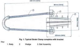 | |||||

| TECHNICAL SPECIFICATION | Doc Number:Version: 1 | |||
| CODE: | DESCRIPTION OF MATERIAL: | Page 2 of 2 | ||
| STRAIN CLAMP FOR AERIAL BUNDLED CABLE (ABC) 25-95 MILLIMETRE | ||||

NOTES:
The clamp shall be designed to anchor LV-ABC cable with insulated conductor and suitable for use at the terminal poles, section poles and at road crossings to carry the tension at the end of the line.
The clamp shall consist of an aluminium alloy corrosion resistant castled body, bail of stainless steel and self-adjusting plastic wedges which shall anchor/hold the neutral conductor without damaging the insulation and shall be of weather and Ultra-Violet resistant polymer.
The clamp shall be designed to be easily fixed to the poles eye hook.
The clamp shall be supplied with a stainless-steel flexible Rope to connect the Clamp to the support.
A wear resistant moveable saddle shall be un-loosely fitted on the Rope to prevent abrasion at the point of fitting into the support.
Locking mechanism shall be wedge type self-locking. Wedges shall be made of high strength, climatic resistance Engineering Plastic with glass fibre.
 | TECHNICAL SPECIFICATION | Doc Number:Version: 1 | ||
| CODE: | DESCRIPTION OF MATERIAL: | Page 1 of 2 | ||
| SERVICE CLAMP FOR AERIAL BUNDLED CABLE (ABC) 4-10 MILLIMETRE | ||||

| ITEM | TECHNICAL DESCRIPTION | UNIT | REA REQUIREMENTS | BIDDER'S OFFER | |
| 1 | Description | Service Clamp for Aerial Bundled Cable (ABC) 4-10mm | |||
| 2 | Rated Voltage | kV | 0.6 | ||
| 3 | Number of Cores | No. | 02 | ||
| 4 | Applicable to Conductor Size | Phase Conductor | $mm^2$ | 4-10 | |
| Neutral Conductor | $mm^2$ | 4-10 | |||
| 5 | Materials for Non-Metallic parts of Fitting | Ultraviolet stabilized and fire retardant materials | |||
| 6 | Materials for Ferrous parts of fitting | Hot Dip Galvanized | |||
| 7 | Colour of Fitting Insulating Parts | Black | |||
| 8 | Operating Ambient Temperature | °C | 1-40 | ||
| 9 | Minimum Breaking Load | kN | 2.5 | ||
| 10 | Relative Humidity | % | 85 | ||
| 11 | Altitude | $m^2$ | 1400 | ||
| 12 | Previous type Tests results/ certificate to be provided upon client request: | Dielectric of fitting mounted on cable | Yes/No | Yes | |
| Accelerated weathering test | Yes/No | Yes | |||
| Tensile Test | Yes/No | Yes | |||
| 13 | Drawings showing design details to be provided with the bid | Yes/No | Yes | ||
| 14 | Quality assurance certificate to be provided with the bid | Yes/No | Yes | ||
| 15 | Routine tests to be provided on delivery | Yes/No | Yes | ||
| 16 | Applicable Standards | PIESA 1018-4 | |||

此块没有可展示内容,保留原始结构以供复核。
| TECHNICAL SPECIFICATION | Doc Number:Version: 1 | |||
| CODE: | DESCRIPTION OF MATERIAL: | Page 2 of 2 | ||
| SERVICE CLAMP FOR AERIAL BUNDLED CABLE (ABC) 4-10 MILLIMETRE | ||||

NOTES:
The clamp shall be designed to anchor insulated service cable, XLPE insulated, armoured/unarmoured PVC sheathed for tensioning the service cable on poles to ensure the proper installation of service cables and connectors.
The clamp shall be designed to be easily fixed to the poles by eye hook.
The clamp shall be supplied with a stainless-steel flexible Rope to connect the Clamp to the support.
The design shall be such that the parts do not separate when the fittings are being installed on the service cable. Any wedges used shall be attached to the clamp body.
Locking mechanism shall be wedge type self-locking. Wedges shall be made of high strength, climatic resistance Engineering Plastic with glass fibre.
| TECHNICAL SPECIFICATION | Doc Number:Version: 1 | ||
| CODE: | DESCRIPTION OF MATERIAL: | Page 1 of 2 | ||
| PIGTAIL BOLT M10x250 MILLIMETRES | ||||

| ITEM | TECHNICAL DESCRIPTION | UNIT | REA REQUIREMENTS | BIDDER'S OFFER |
| 1 | Description | M10x250mm Pigtail Bolt c/w with 2 nuts, 2 round washers and 2 square curved washers | ||
| 2 | Bolt Diameter | mm | M10 | |
| 3 | Bolt length excluding the eye hook | mm | 250 | |
| 4 | Thread length | mm | 100 | |
| 5 | Unthreaded Length | mm | 150 | |
| 6 | Ultimate Tensile Strength (UTS) | kN | 20 | |
| 7 | Material | Mild Steel; Steel Grade to BS 4360 | ||
| 8 | Corrosion protection | Hot Dip Galvanized | ||
| 9 | Dimensions and Tolerances | To BS 4190 | ||
| 10 | Thickness of washers | mm | 5 | |
| 11 | Operating Ambient Temperature | °C | 1-40 | |
| 12 | Relative Humidity | % | 85 | |
| 13 | Altitude | m | 1400 | |
| Other requirements | ||||
| 14 | Drawings showing dimensions to be provided with the bid | Yes/No | Yes | |
| 15 | Previous type test of steel to be provided upon client request | Yes/No | Yes | |
| 16 | Quality assurance certificate to be provided with the bid | Yes/No | Yes | |
| 17 | Applicable standard(s) | ISO 898-1 | ||
| TECHNICAL SPECIFICATION | Doc Number:Version: 1 | |||
| CODE: | DESCRIPTION OF MATERIAL: | Page 2 of 2 | ||
| PIGTAIL BOLT M10x250 MILLIMETRES | ||||

NOTES:
It is recommended that for applications generally the thread length should be at least one third the bolt length as per the dimensions indicated above.
Pigtail eye hooks bolts shall be suitable for mounting through wood poles (by single bolt) and attachment to pre-stressed round concrete poles by use of universal pole clamps.
Pigtail eye hooks bolts shall be designed as to hold both suspension clamps and strain (dead-end) clamps and shall be of wood type or concrete type as per figure below
Pigtail eye hooks bolts shall be made of forged hot dip galvanized steel. The manufacture shall not involve cold bending or welding (or both).
Pigtail eye hooks bolts shall be manufactured from grade 4.8 material in accordance with ISO 898-1 whereas nuts shall be manufactured from grade 5 material in accordance with ISO 898-1.
 | TECHNICAL SPECIFICATION | Doc Number:Version: 1 | ||
| CODE: | DESCRIPTION OF MATERIAL: | Page 1 of 1 | ||
| PIGTAIL SCOTCH SCREW M10 | ||||

| ITEM | TECHNICAL DESCRIPTION | UNIT | REA REQUIREMENTS | BIDDER'S OFFER |
| 1 | Description | M10 Pigtail Scotch Screw with wood threads | ||
| 2 | Screw Diameter | mm | M10 | |
| 3 | Length | mm | 170 | |
| 4 | Thread length | mm | 90 | |
| 5 | Ultimate Tensile Strength (UTS) | kN | 20 | |
| 6 | Material | Mild Steel; Steel Grade to BS 4360 | ||
| 7 | Corrosion protection | Hot Dip Galvanized to BS 729 | ||
| 8 | Dimensions and Tolerances | To BS 4190 | ||
| 9 | Operating Ambient Temperature | °C | 1-40 | |
| 10 | Relative Humidity | % | 85 | |
| 11 | Altitude | m | 1400 | |
| Other requirements | ||||
| 12 | Drawings showing dimensions to be provided with the bid | Yes/No | Yes | |
| 13 | Previous type test of steel to be provided upon client request | Yes/No | Yes | |
| 14 | Quality assurance certificate to be provided with the bid | Yes/No | Yes | |
| 15 | Applicable standard(s) | ISO 898-1 | ||
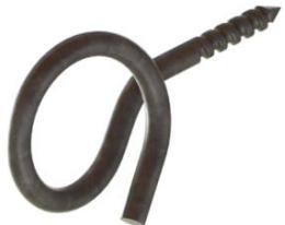 | ||||

NOTES:
Pigtail Scotch screw shall be suitable for screwing directly into wooden pole and for securing into brick wall when used with P16 plastic wall plug.
The screws shall have adequately adjusted threads that shall withstand a high pullout resistance and optimum conditions for the specific field of application.
The screws shall be made from hot dip galvanized steel with minimum tensile strengths conforming to those of the ABC cables.
| TECHNICAL SPECIFICATION | Doc Number:Version: 1 | ||
| CODE: | DESCRIPTION OF MATERIAL: | Page 1 of 2 | ||
| INSULATION PIECING CONNECTOR (IPC) FOR AERIAL BUNDLED CABLE (ABC) 25-95/25-95 MILLIMETRE | ||||

| ITEM | TECHNICAL DESCRIPTION | UNIT | REA REQUIREMENTS | BIDDER'S OFFER | |
| 1 | Description | Insulation Piecing Connector (IPC) for Aerial Bundled Cable (ABC) 25-95/25-95mm | |||
| 2 | Rated Voltage | kV | 0.6 | ||
| 3 | Applicable to Main Core Size | mm | 25-95 | ||
| 4 | Applicable to Branch Core Size | mm | 25-95 | ||
| 5 | Materials for Non-Metallic parts of Fitting | Ultraviolet stabilized and fire retardant materials | |||
| 6 | Materials for Contact Plates of fitting | Tinned Copper | |||
| 7 | Colour of Fitting Insulating Parts | Black | |||
| 8 | Operating Ambient Temperature | °C | 1-40 | ||
| 9 | Relative Humidity | % | 85 | ||
| 10 | Altitude | m | 1400 | ||
| 11 | Exposure to Sunlight | Yes/No | Yes | ||
| 12 | Previous type Tests results/ certificate to be provided upon client request: | Dielectric and Water Tightness | Yes/No | Yes | |
| Electrical Ageing | Yes/No | Yes | |||
| Tensile Test | Yes/No | Yes | |||
| 13 | Drawings showing design details to be provided with the bid | Yes/No | Yes | ||
| 14 | Quality assurance certificate to be provided with the bid | Yes/No | Yes | ||
| 15 | Routine tests to be provided on delivery | Yes/No | Yes | ||
| 16 | Applicable Standards | BS EN 50483-1&4 PIESA 1018-5 | |||

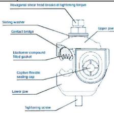
| TECHNICAL SPECIFICATION | Doc Number:Version: 1 | |||
| CODE: | DESCRIPTION OF MATERIAL: | Page 2 of 2 | ||
| INSULATION PIECING CONNECTOR (IPC) FOR AERIAL BUNDLED CABLE (ABC) 25-95/25-95 MILLIMETRE | ||||

NOTES
The IPC must perform piercing and connection on Main and Branch cable simultaneously.
The IPC shall have a rigid removable end cap which can be slide fitted onto the Main connector body on either right or left by the installer (depending on site requirement) for sealing the cut end of the branch cable. Once the connector is fitted, it should not be possible to remove the cap without removing the connector as per figure below.
All the metallic parts of the IPC should be corrosion resistant and there should not be any appreciable change in contact resistance & temperature after overloads & load cycling.
The housing shall be made entirely of mechanical and weather resistant plastic insulation material and no metallic part outside the housing is acceptable except for the tightening bolt.
The connectors shall be totally insulated with no loose parts. They shall be totally weather and moisture proof so that no water or moisture can enter through the pierced holes on the cable insulation.
| TECHNICAL SPECIFICATION | Doc Number:Version: 1 | ||
| CODE: | DESCRIPTION OF MATERIAL: | Page 1 of 2 | ||
| INSULATION PIECING CONNECTOR (IPC) FOR AERIAL BUNDLED CABLE (ABC) 16-95/1.5-10 MILLIMETRE | ||||

| ITEM | TECHNICAL DESCRIPTION | UNIT | REA REQUIREMENTS | BIDDER'S OFFER | |
| 1 | Description | Insulation Piecing Connector (IPC) for Aerial Bundled Cable (ABC) 16-95/1.5-10mm | |||
| 2 | Rated Voltage | kV | 0.6 | ||
| 3 | Applicable to Main Core Size | mm | 16-95 | ||
| 4 | Applicable to Branch Core Size | mm | 1.5-10 | ||
| 5 | Materials for Non-Metallic parts of Fitting | Ultraviolet stabilized and fire retardant materials | |||
| 6 | Materials for Contact Plates of fitting | Tinned Copper | |||
| 7 | Colour of Fitting Insulating Parts | Black | |||
| 8 | Operating Ambient Temperature | °C | 1-40 | ||
| 9 | Relative Humidity | % | 85 | ||
| 10 | Altitude | m | 1400 | ||
| 11 | Exposure to Sunlight | Yes/No | Yes | ||
| 12 | Previous type Tests results/ certificate to be provided upon client request: | Dielectric and Water Tightness | Yes/No | Yes | |
| Electrical Ageing | Yes/No | Yes | |||
| Tensile Test | Yes/No | Yes | |||
| 13 | Drawings showing design details to be provided with the bid | Yes/No | Yes | ||
| 14 | Quality assurance certificate to be provided with the bid | Yes/No | Yes | ||
| 15 | Routine tests to be provided on delivery | Yes/No | Yes | ||
| 16 | Applicable Standards | BS EN 50483-1&4 PIESA 1018-5 | |||


| TECHNICAL SPECIFICATION | Doc Number:Version: 1 | |||
| CODE: | DESCRIPTION OF MATERIAL: | Page 2 of 2 | ||
| INSULATION PIECING CONNECTOR (IPC) FOR AERIAL BUNDLED CABLE (ABC) 16-95/1.5-10 MILLIMETRE | ||||

NOTES
The IPC must perform piercing and connection on Main and Branch cable simultaneously.
The IPC shall have a rigid removable end cap which can be slide fitted onto the main connector body on either right or left by the installer (depending on site requirement) for sealing the cut end of the branch cable. Once the connector is fitted, it should not be possible to remove the cap without removing the connector as per figure below
All the metallic parts of the IPC should be corrosion resistant and there should not be any appreciable change in contact resistance & temperature after overloads & load cycling.
The housing shall be made entirely of mechanical and weather resistant plastic insulation material and no metallic part outside the housing is acceptable except for the tightening bolt.
The connectors shall be totally insulated with no loose parts. They shall be totally weather and moisture proof so that no water or moisture can enter through the pierced holes on the cable insulation.
| TECHNICAL SPECIFICATION | Doc Number:Version: 1 | ||
| CODE: | DESCRIPTION OF MATERIAL: | Page 1 of 1 | ||
| INSULATION END CAP | ||||

| ITEM | TECHNICAL DESCRIPTION | UNIT | REA REQUIREMENTS | BIDDER'S OFFER |
| 1 | Description | Cable Insulation Sealing End Cap | ||
| 2 | Cable Size | $mm^2$ | 25-95 | |
| 3 | Elongation | % | 350 | |
| 4 | Water Absorption | % | <0.2 | |
| 5 | Heat Shrink Material | Cross Linked Polyolefin | ||
| 6 | Degree of Protection | IP68 | ||
| 7 | Colour | Black | ||
| 8 | Minimum Tensile Strength | Mpa | 12 | |
| 9 | Minimum Breaking Load | kN | 0.35 | |
| 10 | Operating Ambient Temperature | °C | 1-40 | |
| 11 | Relative Humidity | % | 85 | |
| 12 | Altitude | m | 1400 | |
| 13 | Exposure to Sunlight | Yes/No | Yes | |
| Other requirements | ||||
| 14 | Drawings showing dimensions to be provided with the bid | Yes/No | Yes | |
| 15 | Previous type test of steel to be provided upon client request | Yes/No | Yes | |
| 16 | Quality assurance certificate to be provided with the bid | Yes/No | Yes | |
| 17 | Applicable standard(s) | BS EN 50483 & PIESA 1018-5 | ||

NOTES:
End sealing caps shall be insulated and provide protection against the ingress of moisture and ensure that the system is fully insulated. They shall be manufactured and tested as per BS EN 50483.
The caps shall be permanent applied, range taking and suitable for installation on 16mm2 -35mm2 ABC cables.
The caps shall not be push fit as accidental contacts could result in them being removed and exposing the live cores.
Cable End Sealing Caps shall have the following features:
o Quick and fool-proof installation using simple tools.
o A strong and permanent environmental seal.
o Excellent resistance to weathering, moisture contamination & adverse environmental conditions.
o Special adhesive lining provides seal on irregular cable sheaths.
o Valved end Cap available for pressurized application.
| TECHNICAL SPECIFICATION | Doc Number:Version: 1 | ||
| CODE: | DESCRIPTION OF MATERIAL: | Page 1 of 2 | ||
| CABLE TIE HEAVY DUTY | ||||

| ITEM | TECHNICAL DESCRIPTION | UNIT | REA REQUIREMENTS | BIDDER'S OFFER |
| 1 | Description | Cable Tie Black Polyamide 6.6 Heavy Duty | ||
| 2 | Width (A) | mm | 8.8-12.7 | |
| 3 | Length (B) | mm | 180 | |
| 4 | Thickness (C) | mm | 2 | |
| 5 | Material | Weather and UV-Resistant Nylon Polyamide 6.6 | ||
| 6 | Locking Type | Locking Non-Releasable | ||
| 7 | Colour | Black | ||
| 8 | Minimum Loop Tensile Strength | kN | 0.55 | |
| 9 | Minimum Breaking Load | kN | 0.35 | |
| 10 | Operating Ambient Temperature | °C | 1-40 | |
| 11 | Relative Humidity | % | 85 | |
| 12 | Altitude | m | 1400 | |
| 13 | Exposure to Sunlight | Yes/No | Yes | |
| Other requirements | ||||
| 14 | Drawings showing dimensions to be provided with the bid | Yes/No | Yes | |
| 15 | Previous type test of steel to be provided upon client request | Yes/No | Yes | |
| 16 | Quality assurance certificate to be provided with the bid | Yes/No | Yes | |
| 17 | Applicable standard(s) | PIESA 1020 | ||
| 18 | DrawingTECHNICAL SPECIFICATION | Doc Number:Version: 1 | ||
| CODE: | DESCRIPTION OF MATERIAL: | Page 2 of 2 | ||
| CABLE TIE HEAVY DUTY | ||||
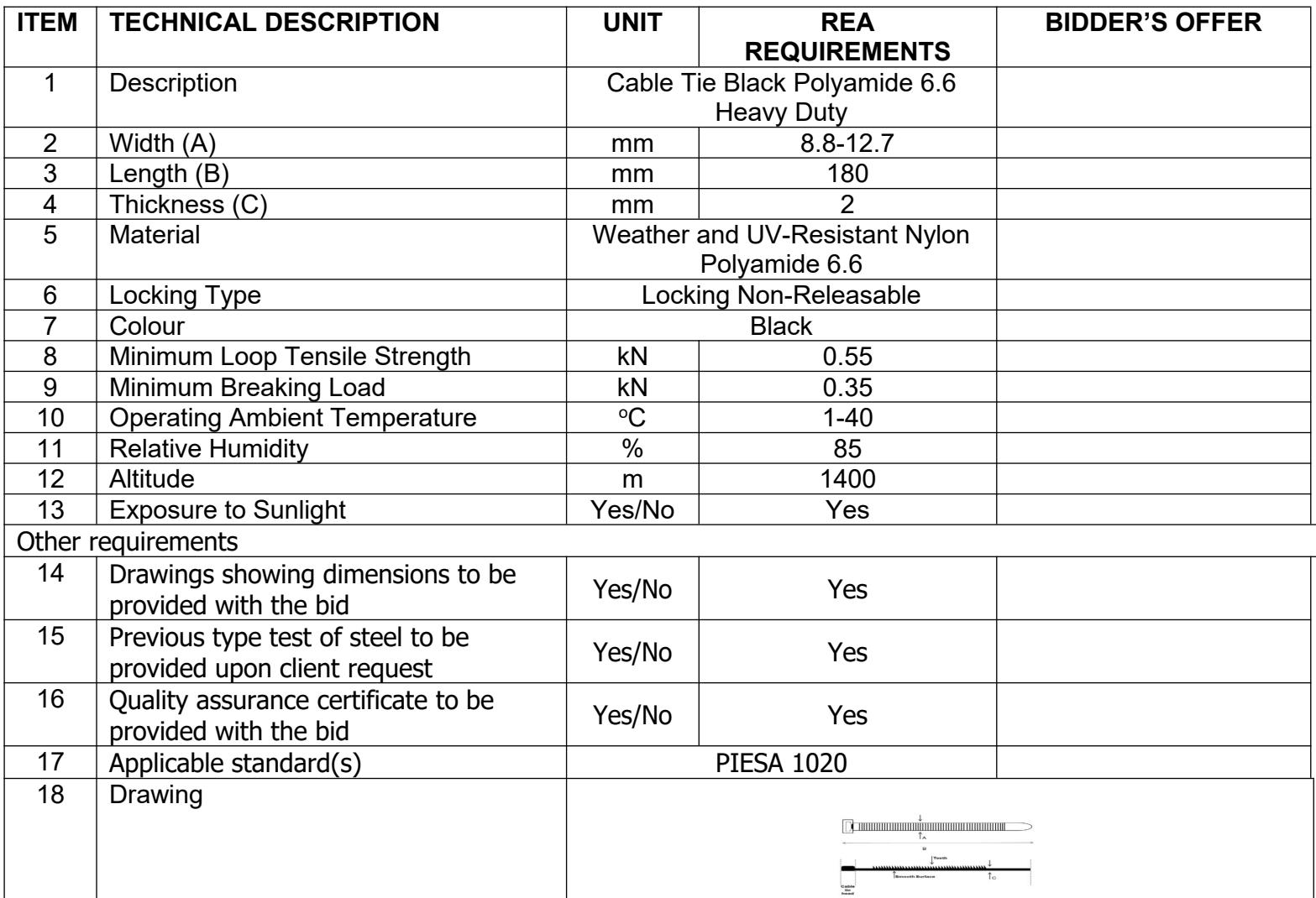
NOTES:
Cable tie shall be suitable for outdoor use
Mechanical strength maintained even in dry climate
The Cable Tie is extensively tested according to Tensile Strength Test and Loop Tensile Test and shall pass UL 94 V-2 flammability tests.
The cable tie shall be heavy duty type single piece assembly of minimum loop tensile strength of 550N; advanced pawl and teeth design, with tail finger grips for easier handling and tightening.
The cable tie shall be tapered to facilitate insertion into the tie clamp.
The cable tie material shall be weather-stabilized, corrosion resistant and unaffected by humidity variation.
Cable ties shall be of uniform quality and shall be free from sharp edges, irregularities or defects that could affect their performance, reliability, or durability.
 | TECHNICAL SPECIFICATION | Doc Number:Version: 1 | ||
| CODE: | DESCRIPTION OF MATERIAL: | Page 1 of 2 | ||
| PRE-INSULATED SLEEVE JOINT | ||||

| ITEM | TECHNICAL DESCRIPTION | UNIT | REA REQUIREMENTS | BIDDER'S OFFER |
| 1 | Description | Pre-Insulated Sleeve Joint | ||
| 2 | Rated Voltage | kV | 0.6/1 | |
| 3 | Length | mm | 98.5 | |
| 4 | Exposure to Sunlight | Yes/No | Yes | |
| 5 | Unthreaded Length | mm | 150 | |
| 6 | Ultimate Tensile Strength (UTS) | kN | 20 | |
| 7 | Material for phase connector | Forged Aluminium | ||
| 8 | Material for phase connector | Aluminium Alloy | ||
| 9 | Insulation Material | Black thermoplastic | ||
| 10 | Operating Ambient Temperature | °C | 1-40 | |
| 11 | Relative Humidity | % | 85 | |
| 12 | Altitude | m | 1400 | |
| Other requirements | ||||
| 13 | Drawings showing dimensions to be provided with the bid | Yes/No | Yes | |
| 14 | Previous Type Test Report/Certificate to be provided upon client request | Yes/No | Yes | |
| 15 | Quality Assurance ISO Certificate to be provided with the bid | Yes/No | Yes | |
| TECHNICAL SPECIFICATION | Doc Number:Version: 1 | |||
| CODE: | DESCRIPTION OF MATERIAL: | Page 2 of 2 | ||
| PRE-INSULATED SLEEVE JOINT | ||||

NOTES:
The sleeves shall compose of:
o An aluminium (phase) or aluminium alloy (neutral) sleeve with a stop in the middle.
o A black thermoplastic sealed tube with a flexible elastomer ring.
o Neutral contact grease in the tube which improve the contact area and protect the aluminium against oxidation.
The crimping shall be realized on the plastic part according to the marks on the body of the sleeve.